A motion transformation guide rail type arc core pulling mechanism
A technology for changing guide rails and core-pulling mechanisms is applied in the field of arc core-pulling mechanisms, and can solve the problems of complex arc-pulling mechanisms and high energy consumption.
- Summary
- Abstract
- Description
- Claims
- Application Information
AI Technical Summary
Problems solved by technology
Method used
Image
Examples
Embodiment 1
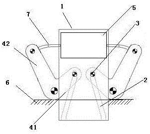
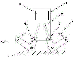
[0018] as attached Figure 1-2 As shown, in this embodiment, a set of two symmetrical motion transformation guide rail type arc swing core-pulling mechanisms is taken as an example, and any one of the motion transformation guide rail type arc swing core pulling mechanisms includes a guide plate 1 and a guide groove 2 , guide pin 3 and L-shaped swing lever 4.
[0019] The L-shaped swing bar 4 includes a first bar 41 and a second bar 42; one end of the first bar 41 is fixedly connected with an end of the second bar 42, and the connection between the first bar 41 and the second bar 42 is fixed in a fixed position. On the first plane 6 that moves vertically relative to the guide plate 1;
[0020] A mold 5 fixedly connected to the guide plate 1 is provided with a guide groove 2 on the guide block, the guide groove 2 forms a certain angle with the vertical direction, and the top of the guide groove 2 is inclined away from the direction of the second rod 42, and the guide pin is set...
Embodiment 2
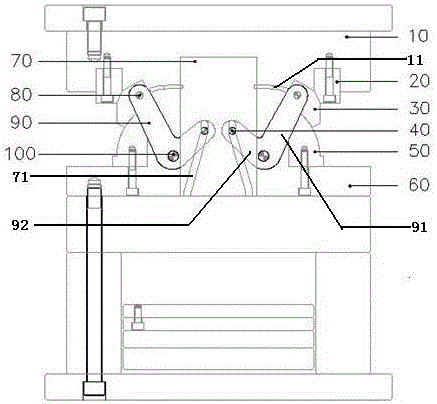
[0026] as attached Figure 3-5 As shown, a motion conversion guide rail type arc core-pulling mechanism provided by the present invention is set on an injection molding machine, and the mold 12 with the core-pulling part 11 is placed on the fixed mold part 10 of the injection molding machine. In this embodiment, it is Take a group of two symmetrical rail-type arc swing core-pulling mechanisms as an example, any one of the guide-rail type arc swing core-pulling mechanisms includes a guide plate 70, a guide groove 71, a guide pin 40, an L-shaped swing rod 90, a lock Tight block 20, arc guide block 50 and slide block 30,
[0027] The L-shaped swing rod 90 includes a first rod 91 and a second rod 92; one end of the first rod 91 is fixedly connected to one end of the second rod 92, and the angle between the first rod and the second rod is 30-120 degrees, and The connection between the first rod 91 and the second rod 92 is fixed on the movable mold part 60 of the injection molding ...
PUM
 Abstract
Description
Claims
Application Information
 - R&D
- Intellectual Property
- Life Sciences
- Materials
- Tech Scout
- Unparalleled Data Quality
- Higher Quality Content
- 60% Fewer Hallucinations
Browse by: Latest US Patents, China's latest patents, Technical Efficacy Thesaurus, Application Domain, Technology Topic, Popular Technical Reports.
© 2025 PatSnap. All rights reserved.Legal|Privacy policy|Modern Slavery Act Transparency Statement|Sitemap|About US| Contact US: help@patsnap.com


