Transverse knotting mechanism of automatic shoelace tying machine

An automatic technology for tying shoelaces, applied to footwear, shoe ties, clothing, etc., to achieve the effects of high efficiency, short knotting time, and ingenious design

Pending Publication Date: 2020-07-24
ZHEJIANG COLLEGE OF ZHEJIANG UNIV OF TECHOLOGY
View PDF0 Cites 0 Cited by
  • Summary
  • Abstract
  • Description
  • Claims
  • Application Information

AI Technical Summary

Problems solved by technology

[0005] The purpose of the present invention is to provide a horizontal knotting mechanism of an automatic

Method used


Image

  • Transverse knotting mechanism of automatic shoelace tying machine
  • Transverse knotting mechanism of automatic shoelace tying machine
  • Transverse knotting mechanism of automatic shoelace tying machine

Examples


Embodiment

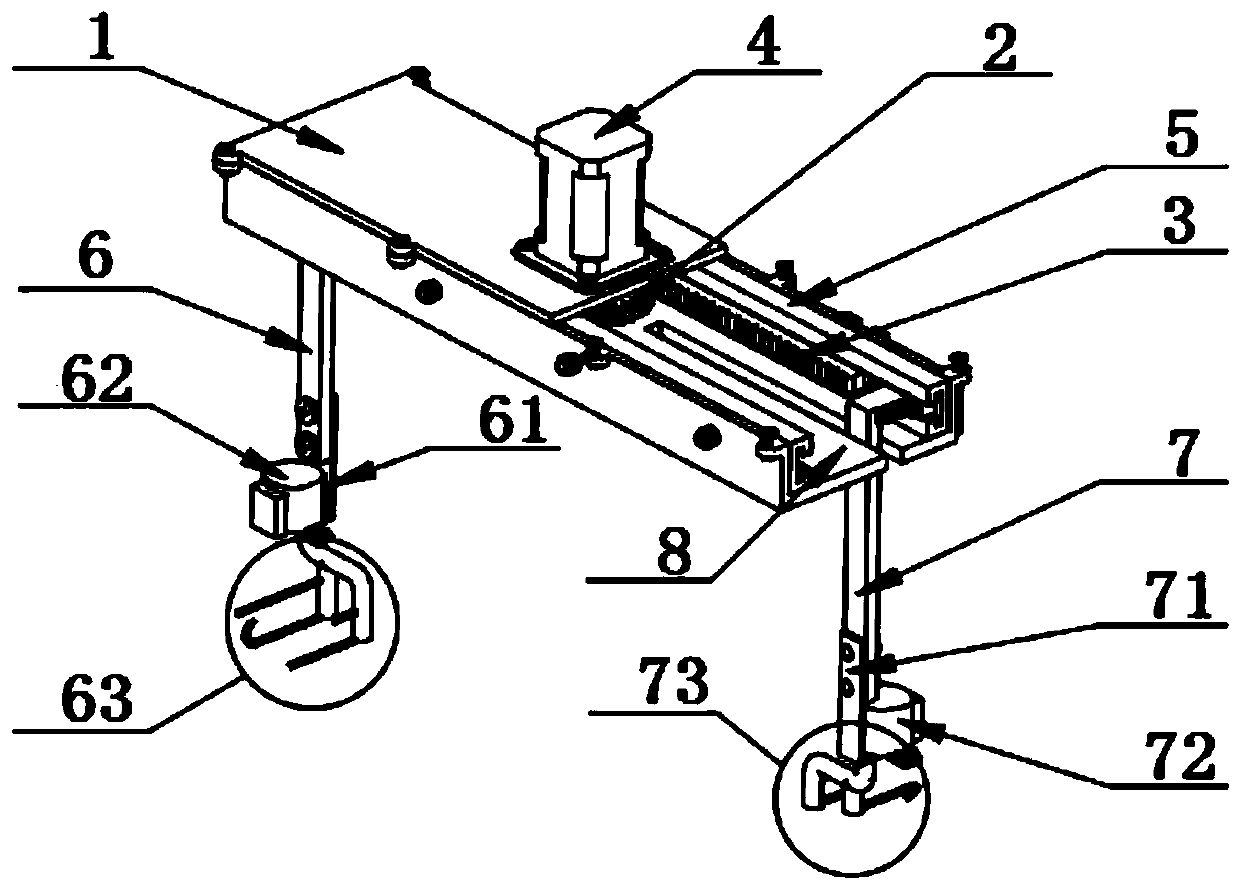
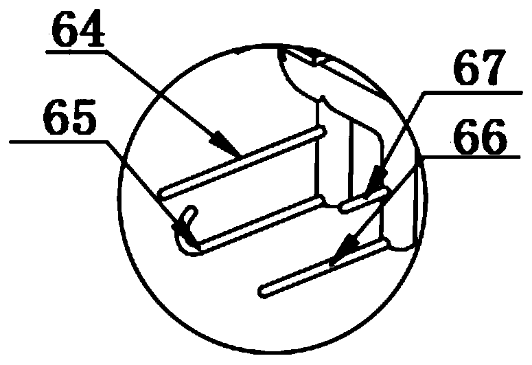
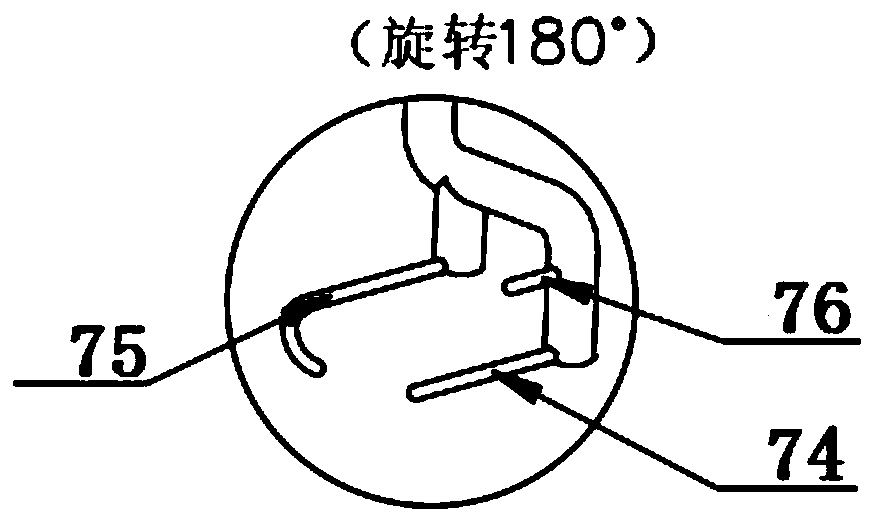
[0033] Embodiment: a kind of horizontal knot mechanism of automatic shoelace machine, as Figure 1-4 As shown, the automatic shoelace machine is provided with a shoe support plate 9 for supporting shoes, and the horizontal knotting mechanism is arranged above the shoe support plate 9 . The horizontal knotting mechanism includes a housing 1, in which a driving gear 2 and two racks 3 meshing with the driving gear 2 are arranged, and the two racks 3 are parallel to each other. A gear drive motor 4 is fixedly installed on the top of the housing 1, the output shaft of the gear drive motor 4 passes through the top surface of the housing 1 and is connected with the rotating shaft of the driving gear 2, and the driving gear 2 can be driven to rotate by the gear drive motor 4; the housing 1 There are guide rails 5 along the length direction on the front and rear sides of the inner side respectively. T-shaped slots are opened on the guide rails 5. The back of the rack 3 matches the T-sh...


PUM


Abstract

A transverse knotting mechanism of an automatic shoelace tying machine comprises a shell, a driving gear and two racks meshed with the driving gear are arranged in the shell, the driving gear is driven by a gear driving motor, guide rails are arranged on the front side and the rear side in the shell respectively, and the racks can slide along the guide rails respectively; the outward ends of the two racks are connected with a vertically-downward left transmission rod and a vertically-downward right transmission rod respectively, the bottom end of the left transmission rod and the bottom end ofthe right transmission rod are connected with a left motor and a right motor respectively, and output shafts of the left motor and the right motor are connected with a left drag hook set and a rightdrag hook set respectively. The left drag hook set and the right drag hook set can flexibly move like the fingers of a person, and automatic knotting of shoelaces is achieved; multiple complex actionscan be completed on the basis of a simple structure, the problem of automatic knotting of shoelaces is solved, and the knotting mechanism is ingenious in design, efficient in action, short in knotting time and high in efficiency.

Description

technical field [0001] The invention relates to the technical field of automatic shoelace tying, in particular to a horizontal knotting mechanism of an automatic shoelace tie machine. Background technique [0002] There are some hand-disabled people, patients with lumbar diseases, hypertensive patients, pregnant women and other groups among the social population in our country. It is difficult for the above-mentioned people to complete the process of tying shoelaces due to their aging body or inconvenient movement. [0003] After investigation, there has not been a device capable of stabilizing shoelaces on the market in my country at present, and the existing related devices also have a series of problems such as large volume, complex structure, and unsuitability for home use. In order to effectively help people with hand disabilities, patients with lumbar spine diseases, hypertensive patients, pregnant women, etc. to solve the difficult problem of tying shoelaces, it is ur...

Claims


Application Information

Patent Timeline
IPC IPC(8): A43C7/00
CPCA43C7/00
Inventor 刘健肖涛邹涛姜博鑫方清康钱宋杭
Owner ZHEJIANG COLLEGE OF ZHEJIANG UNIV OF TECHOLOGY
Why Eureka
Try Eureka