Pressing mold mechanism

A technology of stamping die and adjusting mechanism, which is applied in the field of stamping die, can solve the problems of affecting the feeding process, unfavorable stamping die stamping of the strip, and arching of the strip, and achieves the effect of good use effect and simple structure.

Active Publication Date: 2020-07-24
HANGZHOU FUYANG HONGXIANG TECH SERVICES CO LTD
View PDF5 Cites 0 Cited by
  • Summary
  • Abstract
  • Description
  • Claims
  • Application Information

AI Technical Summary

Problems solved by technology

[0002] In the existing stamping process at present, ordinary small hardware parts are usually produced by stamping dies on the metal strip; usually, the punch moves at a high speed, and the strip to be stamped can be realized automatically. High-speed feeding to ensure that the semi-finished parts of the corresponding shape are continuously punched out on the stamped strip at high speed; As far as the stamped strip is concerned, the phenomenon of strip arching is likely to occur during the pushing and stamping process, which affects the smooth progress of the feeding process, and the arched strip is not conducive to stamping by the stamping die
In order to solve the problem that the strip material is arched and affects the feeding, it is necessary to design a material pulling device, and this material pulling device not only needs to adapt to the height of the working platform of different stamping dies, but also adapts to the strip being stamped out by different stamping dies The spacing of the holes, so it is necessary to design a pulling device that can adapt to a wider range of scenarios

Method used


Image

  • Pressing mold mechanism
  • Pressing mold mechanism
  • Pressing mold mechanism

Examples


Embodiment Construction

[0030]The accompanying drawings are all schematic diagrams of the implementation of the present invention, so as to understand the principle of structural operation. The specific product structure and proportional size can be determined according to the use environment and conventional technology.

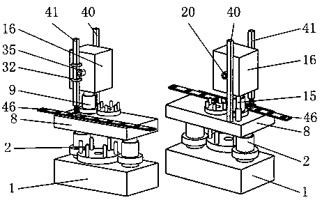
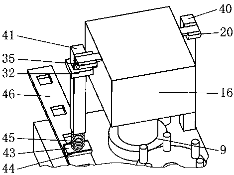
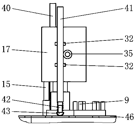
[0031] like figure 1 As shown, it includes base 1, adjustment mechanism A2, lifting plate 8, adjustment mechanism B9, telescopic rod A15, transmission mechanism 16, rack A40, rack B41, telescopic rod B42, semicircular block 43, arc friction pad 44, Pressure spring 45, wherein base 1 is connected with lifting plate 8 above by adjusting mechanism A2, and adjusting mechanism A2 is used for adjusting the height of lifting plate 8; figure 1 , 3 As shown, the lifting plate 8 is connected with the transmission mechanism 16 above through the adjustment mechanism B9 and the telescopic rod A15, and the adjustment mechanism B9 is used to adjust the height of the transmission mechanism 16; a...


PUM


Abstract

The invention belongs to the technical field of pressing molds, and particularly relates to a pressing mold mechanism. The mechanism comprises a base, an adjusting mechanism A, a lifting plate, an adjusting mechanism B and the like, the base fixedly mounted on a pressing mold discharging side platform is connected with the lifting plate on the upper portion through the adjusting mechanism A, the adjusting mechanism A is used for adjusting the height of the lifting plate, the height of a transmission mechanism can be adjusted according to frequency of a pressed strip of a pressing mold, the effective moving distance of a rack B to the strip through a telescopic rod, a semicircular block, and an arc friction pad under different pressing frequencies can be ensured, it is ensured that the pressing frequency is consistent with the moving frequency of the arc friction pad for the strip, and the phenomenon that in the pressing process of a thin strip, arching up happens, and pressing is affected can be effectively avoided.

Description

technical field [0001] The invention belongs to the technical field of stamping dies, in particular to a stamping die mechanism. Background technique [0002] In the existing stamping process at present, ordinary small hardware parts are usually produced by stamping dies on metal strips; usually, the speed of the punch’s up and down movement is high, and the strip that needs to be stamped can realize automatic High-speed feeding to ensure that the semi-finished parts of the corresponding shape are continuously punched out on the stamped strip at high speed; As far as the stamping strip is concerned, the phenomenon of strip arching is likely to occur during the pushing and stamping process, which affects the smooth progress of the feeding process, and the arched strip is not conducive to stamping by the stamping die. In order to solve the problem that the strip material is arched and affects the feeding, it is necessary to design a material pulling device, and this material ...

Claims


Application Information

Patent Timeline
Patent Type & Authority Applications(China)
IPC IPC(8): B21D28/00B21D28/06B21D43/05
CPCB21D28/002B21D28/06B21D43/05
Inventor 林权豪
Owner HANGZHOU FUYANG HONGXIANG TECH SERVICES CO LTD
Why Eureka
Try Eureka