Device for stamping die

A stamping die, L-shaped technology, applied in the field of devices used in stamping dies, can solve the problems of unfavorable stamping die stamping by strips, influence of strips on feeding, and influence on feeding process, etc., and achieves simple structure, avoids locking phenomenon, and is easy to use. effect of effect

Active Publication Date: 2019-07-19
杭州银湖机械弹簧有限公司
View PDF7 Cites 1 Cited by
  • Summary
  • Abstract
  • Description
  • Claims
  • Application Information

AI Technical Summary

Problems solved by technology

[0002] In the existing stamping process at present, ordinary small hardware parts are usually produced by stamping dies on the metal strip; usually, the punch moves at a high speed, and the strip to be stamped can be realized automatically. High-speed feeding to ensure that the semi-finished parts of the corresponding shape are continuously punched out on the stamped strip at high speed; As far as the stamped strip is concerned, the phenomenon of strip arching is likely to occur during the pushing and stamping process, which affects the smooth progress of the feeding process, and the arched strip is not conducive to stamping by the stamping die
In order to solve the problem that the strip material is arched and affects the feeding, it is necessary to design a material pulling device, and this material pulling device not only needs to adapt to the height of the working platform of different stamping dies, but also adapts to the strip being stamped out by different stamping dies The spacing of the holes, so it is necessary to design a pulling device that can adapt to a wider range of scenarios

Method used


Image

  • Device for stamping die
  • Device for stamping die
  • Device for stamping die

Examples


Embodiment Construction

[0036] The drawings are schematic diagrams of the implementation of the present invention to facilitate the understanding of the operating principle of the structure. The specific product structure and proportional size can be determined according to the use environment and conventional technology.

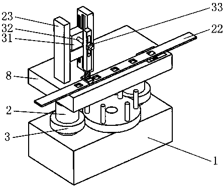
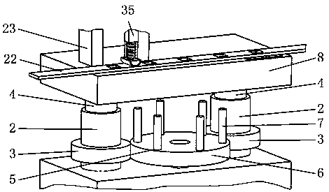
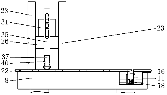
[0037] Such as figure 1 As shown, it includes the base 1, the screw sleeve 2, the gear A3, the screw 4, the adjustment mechanism 5, the lifting plate 8, the slider A11, the limit block 16, the spring A18, the guide rail 23, the slider B26, the L-shaped plate B29, Electric drive module 31, drive shaft 32, nut 33, positioning ring 34, swing plate 35, telescopic rod 37, semicircular block 38, arc friction pad 39, spring D40, such as figure 2 As shown, the two screw sleeves 2 matched with the upper end bearing of the base 1 are respectively connected to the lifting plate 8 through the screw 4 screwed therewith; the adjustment mechanism 5 is installed on the upper end of the base 1, and i...


PUM


Abstract

The invention belongs to the technical field of a stamping die, and in particular relates to a device for the stamping die. The device for the stamping die comprises a base, thread sleeves, threaded rods, a lifting plate, an electric driving module, etc., wherein the base is fixedly arranged on the discharging side of the stamping die, and the two thread sleeves matched with a bearing at the upperend of the base are connected with the lifting plate respectively through the threaded rods screwed with the two thread sleeves. According to the device for the stamping die, the height of the electric driving module can be adjusted according to the frequency of stamping a material strap of the stamping die, and the effective stirring distance of a swing plate to the material strap through a telescopic rod, a semicircular block and an arc-shaped friction pad under different stamping frequencies is ensured; and further, the fact that the stamping frequency is consistent with the stirring frequency of the arc-shaped friction pad to the material strap is ensured. A limiting block matched with the material strap prevents the material strap from being pulled back under external force, and theeffectiveness of stirring the material strap forward of the swing plate through the telescopic rod, the semicircular block and the arc-shaped friction pad is ensured.

Description

Technical field [0001] The invention belongs to the technical field of stamping dies, and in particular relates to a device for stamping dies. Background technique [0002] At present, in the existing stamping process, a stamping die is usually used to stamp and form a metal strip to make ordinary hardware parts; under normal circumstances, the up and down movement speed of the punch is relatively high, and the strip that needs to be stamped can realize automatic High-speed feeding to ensure continuous high-speed punching of semi-finished parts of the corresponding shape on the stamped strip; in the stamping process, most of the stamped strips in the prior art adopt a push-type feeding method; for thinner thickness As far as the stamping strip is concerned, it is very likely that the tape will be arched during the push and stamping process, which will affect the smooth progress of the feeding process, and the tape that has arched is not conducive to the stamping of the stamping d...

Claims


Application Information

Patent Timeline
Patent Type & Authority Applications(China)
IPC IPC(8): B21D37/10B21D37/12B21C51/00
CPCB21C51/00B21D28/26B21D28/34B21D43/003B21D43/04
Inventor 林权豪
Owner 杭州银湖机械弹簧有限公司
Why Eureka
Try Eureka