Inspection tool for assisting printed circuit board with structural member in automatic optical inspection

An automatic optical inspection and printed circuit board technology, which is applied in measuring devices, material analysis through optical means, scientific instruments, etc., can solve problems such as the inability to implement automatic optical inspection of printed circuit boards with structural parts, and achieve optimal inspection The effect of the process

Pending Publication Date: 2020-07-31
CHINESE AERONAUTICAL RADIO ELECTRONICS RES INST
View PDF6 Cites 0 Cited by
  • Summary
  • Abstract
  • Description
  • Claims
  • Application Information

AI Technical Summary

Problems solved by technology

[0004] The object of the present invention is to provide an inspection tool for automatic optical inspection of printed circuit boards with structural parts, which can realize automatic optical inspection of printed circuit boards "after the structural parts are installed", and overcome the existing automatic optical inspection. Due to "focus limitation", the detector cannot implement automatic optical inspection of printed circuit boards with structural parts, which optimizes the inspection process

Method used


Image

  • Inspection tool for assisting printed circuit board with structural member in automatic optical inspection
  • Inspection tool for assisting printed circuit board with structural member in automatic optical inspection
  • Inspection tool for assisting printed circuit board with structural member in automatic optical inspection

Examples


Embodiment Construction

[0022] The inspection tool for automatic optical inspection of printed circuit boards with structural components provided by the present invention will be further described in detail below in conjunction with the accompanying drawings and embodiments.

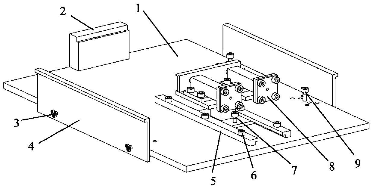
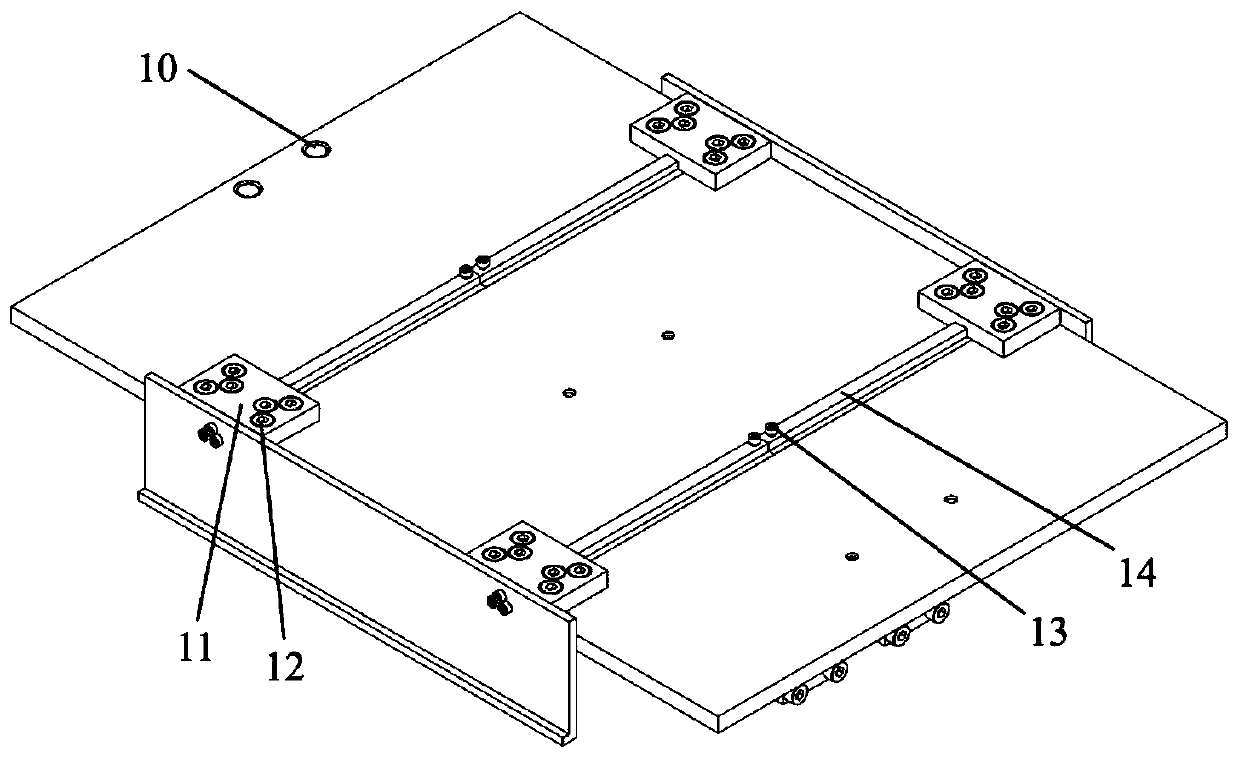
[0023] like figure 1 , 2 As shown, this embodiment shows an inspection tool for automatic optical inspection of printed circuit boards with structural components, including a tray 1 , a fixed side plate 2 , a movable base 8 and base guide rails 5 .

[0024] The fixed side plate 2 is fixed on one side of the tray 1 by two fixed side plate bolts 10, the top of the fixed side plate 2 is provided with a step facing the side of the tray 1, and the height from the bottom surface of the step to the tray 1 is the printed circuit with structural parts. The height of the board.

[0025] Two base rails 5 are perpendicular to the fixed side plate 2, fixed on the front of the tray 1 by six base rail bolts 6, and the movable base 8 is limi...


PUM


Abstract

The invention discloses an inspection tool for assisting a printed circuit board with a structural member in automatic optical inspection. The inspection tool comprises a tray (1), a fixed side plate(2), a movable base (8) and a base guide rail (5), wherein the fixed side plate (2) is fixed to one side of the tray (1) through a fixed side plate bolt (10), a step is arranged on the side, facing the tray (1), of the top end of the fixed side plate (2), and the height from the bottom surface of the step to the tray (1) is the height of the printed circuit board with a structural member; two baseguide rails (5) are vertical to the fixed side plate (2); the base guide rails (5) are fixed to the front face of the tray (1) through base guide rail bolts (6); a movable base (8) is limited betweenthe two base guide rails; and after one end of the printed circuit board with the structural member is placed on the fixed side plate (2), the movable base (8) is moved to fix the other end of the printed circuit board with the structural member. Thus, automatic optical inspection of the printed circuit board after installation of the structural member can be realized.

Description

technical field [0001] The invention belongs to the technical field of inspection of printed circuit boards, and in particular relates to an inspection tool for automatic optical inspection of printed circuit boards with structural parts. Background technique [0002] With the development of science and technology, printed circuit boards have been widely used in aviation, aerospace, automobile, medical and other fields. Due to the small size, large quantity, and complex types of components, defects such as wrong parts, missing parts, and displacement of components will occur during the manufacturing process of printed circuit boards, which will affect the functional performance of printed circuit boards. At present, the inspection of printed circuit boards includes methods such as manual visual inspection and automatic optical inspection. Automatic optical inspection is to use optical means to obtain the surface state of the finished product, compare it with the qualified p...

Claims


Application Information

Patent Timeline
Patent Type & Authority Applications(China)
IPC IPC(8): G01N21/956
CPCG01N21/95607G01N2021/95615G01N2021/95638
Inventor 贾颖高二超董炜钟娴
Owner CHINESE AERONAUTICAL RADIO ELECTRONICS RES INST
Why Eureka
Try Eureka