Ventilation apparatus and method for operating such apparatus

A technology of ventilation device and air conveying device, which is applied in the direction of energy recovery system of ventilation and heating, ventilation system, space heating and ventilation, etc. Aggregation and efficiency improvement

Active Publication Date: 2020-08-14
SIEGENIA AUBI KG
View PDF8 Cites 0 Cited by
  • Summary
  • Abstract
  • Description
  • Claims
  • Application Information

AI Technical Summary

Problems solved by technology

The temporal process for adjusting the closing device into the selected operating mode by means of the ventilation slide is cyclical, so that the air exchange is interrupted during this period, which can adversely affect the air exchange and due to the constant repetition Alternating noise disturbingly affects persons located in the space
Furthermore, heat exchangers and filter elements are flowed through alternately, wherein by splitting the air flow of the ventilation and ventilation medium flow through the heat exchangers into two halves, even only half of the available storage capacity is used. capacity, which adversely affects the degree of heat recovery
Furthermore, it has proven to be disadvantageous that the ventilation and ventilation medium flows alternately flow through the filter element

Method used


Image

  • Ventilation apparatus and method for operating such apparatus
  • Ventilation apparatus and method for operating such apparatus
  • Ventilation apparatus and method for operating such apparatus

Examples


Embodiment Construction

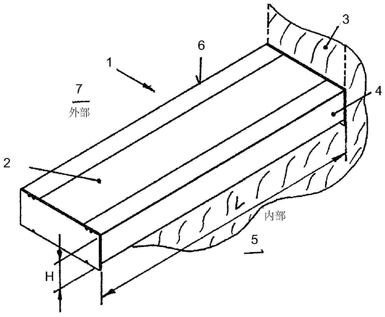
[0037] Attached figure 1 A perspective view of a ventilation device 1 with a housing 2 for simultaneously ventilating and ventilating a space is shown. Ventilation device 1 can be based on figure 1 Fastening in the building wall 3 , which can be designed in particular as a facade wall, is preferably from the inside 5 of the space or, if desired, also from the outside 7 . In this case, the building wall 3 has openings towards the outside 7 which are also conceivable for windows or doors. The ventilation device 1 can also be used in specially designed openings in the building walls 3 .

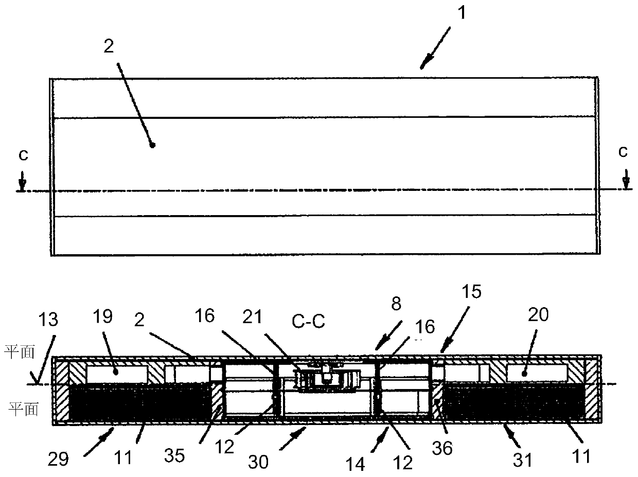
[0038] also, figure 1 and figure 2 It is shown that the housing 2 of the ventilation device 1 forms an upper plane 14 and a lower plane 15 at a height H divided by a central base 13 , wherein the central base 13 is formed in three parts. according to figure 2 The housing 2 is again separated by the closing and opening device 12 in the upper plane 14 over a total length L and the lower pl...


PUM


Abstract

A ventilation apparatus (1) for the supply and removal of air to and from rooms of a building, having a housing (2) which is arranged in a building wall (3) with one side face (4) toward the room interior (5) and with one side face (6) toward the exterior (7), with an air supply medium flow (9) entering the room interior (5) via an air delivery device (8), and an air removal medium flow (10) leaving the room interior (5) to the exterior (7), with a heat storage unit (11) for the transfer of heat from the air removal medium flow (10) to the air supply medium flow (9), and with a closure and opening device (12) for controlling the air flow, wherein the housing (2), being split in the height direction (H) by a partition floor (13), forms an upper level (14) and a lower level (15), and in thelength direction (L) the upper level (14) is divided by the closure and opening device (12) and the lower level (15) is divided by means of partition walls (16), thus forming two upper air flow ducts(17, 18) and two lower air flow ducts (19, 20), wherein the air delivery device (8) consists of a feed air fan (21) for the air supply medium flow (9) and of an exhaust air fan (22) for the air removal medium flow (10), which are continuously operated in an air delivery direction and connect the upper level (14) to the lower level (15), that the upper air flow ducts (17, 18) each have a heat storage unit (11) on the side face (6) of the housing (2) on the upper level (14), and a feed air filter element (23) is to be assigned between the heat storage unit (11) and the exterior (7), through which the air supply and removal medium flows (9, 10) can be made to flow continuously over the full area, reciprocally and in opposite directions in the air flow ducts (17, 18) with the closure and opening device (12) connected upstream, wherein the air supply and removal medium flow (9, 10) in the lower level (15) is made to flow uniformly through the air flow ducts (19, 20), wherein to the side face (6) of the housing (2) in the region of the inlet opening (27) of the lower air flow duct (20) there is arranged an exhaust air filter element (28) through which the air removal medium flow (10) always flows.

Description

technical field [0001] The invention relates to a ventilation device for ventilation and ventilation of at least one room in a building according to the preamble of claim 1 . The invention here relates in particular to a ventilation device with a heat accumulator unit for heat transfer from a ventilation medium flow to a ventilation medium flow, with closing and opening means for controlling the air flow path, wherein in A filter element is provided in the air flow path. Background technique [0002] A ventilation device of this type is already known from DE 3207761 A1. The invention describes a ventilation and ventilation device with recovery of exhaust heat for living and staying spaces, offices, schools, warehouses and work spaces, which has the ability to be mounted on walls and / or Or a box-like housing in an intermediate ceiling, in which two radial fans are provided for the separate input and output of the air flow. For the intake and exhaust, one storage bank each ...

Claims


Application Information

Patent Timeline
Patent Type & Authority Applications(China)
IPC IPC(8): F24F13/20F24F7/08F24F12/00
CPCF24F7/06F24F7/08F24F12/001F24F13/20F24F2012/008Y02B30/56
Inventor 马莱娜·鲍尔克里斯托夫·贝克尔于尔根·萨斯曼斯豪森米歇尔·斯托姆朱利安·格雷贝纳
Owner SIEGENIA AUBI KG
Why Eureka
Try Eureka