Supercharge Your Innovation With Domain-Expert AI Agents!

Optical detection equipment

A technology of optical inspection and equipment, which is applied in optical instrument testing, optical testing for flaws/defects, material analysis through optical means, etc. It can solve problems such as high detection difficulty, many types of defects in non-planar areas, and quality problems

Pending Publication Date: 2020-09-18
BOE TECH GRP CO LTD
View PDF16 Cites 1 Cited by
  • Summary
  • Abstract
  • Description
  • Claims
  • Application Information

AI Technical Summary

Problems solved by technology

Due to the characteristics of the process and the product, there are many types of defects in non-planar areas and the detection is difficult. Conventional Automated Optical Inspection (AOI) equipment appears bright bands or pure black bands when shooting curved surfaces, and cannot clearly capture product defects. , resulting in quality problems

Method used


Image

  • Optical detection equipment
  • Optical detection equipment
  • Optical detection equipment

Examples


Embodiment Construction

[0029] In order for those skilled in the art to better understand the technical solutions of the present disclosure, an optical detection device provided by the present disclosure will be described in detail below with reference to the accompanying drawings.

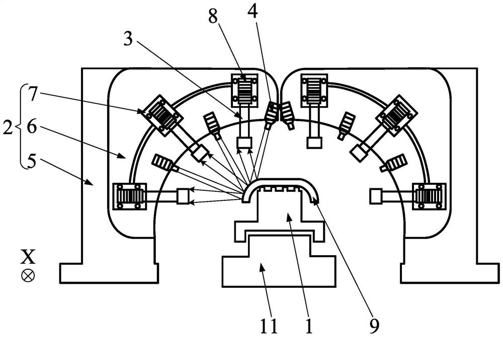
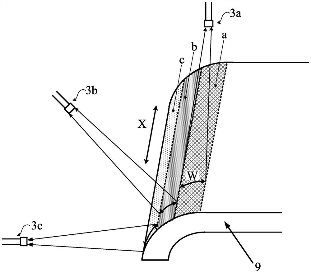
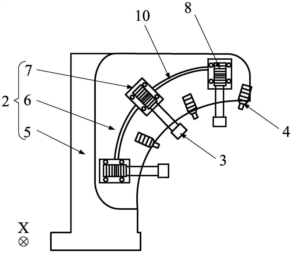
[0030] figure 1 A front view of an optical detection device provided by an embodiment of the present disclosure, such as figure 1 As shown, the optical detection device includes: a stage 1 , a fixed support part 2 , at least one line scan camera 3 and at least one light source 4 . Wherein, the stage 1 is configured to carry the product 9 to be inspected, the fixed support part 2 is located on the side of the stage 1, the line scan camera 3 is arranged on the fixed support part 2, and the line scan camera 3 is configured as an area to be photographed on the surface of the product 9 to be inspected Scan along the preset scanning direction X to obtain corresponding images; the light source 4 is arranged on the fixed suppor...


PUM


Abstract

The invention provides optical detection equipment, and the equipment comprises a carrying platform which is configured to carry a to-be-detected product; a fixed supporting part located on the side face of the carrying platform; at least one line scanning camera arranged on the fixed supporting part, and configured to scan a to-be-shot area on the surface of the to-be-detected product along a preset scanning direction so as to acquire a corresponding image; and at least one light source arranged on the fixed supporting part, one-to-one correspondence with the line scanning cameras, and configured to illuminate positions shot by the corresponding line scanning camera.

Description

technical field [0001] The present disclosure relates to the display field, in particular to an optical detection device. Background technique [0002] With the development of display technology, display products have developed from traditional planar forms to curved surfaces, curved surfaces and even spherical surfaces. Due to the characteristics of the process and the product, there are many types of defects in non-planar areas and the detection is difficult. Conventional Automated Optical Inspection (AOI) equipment appears bright bands or pure black bands when shooting curved surfaces, and cannot clearly capture product defects. , resulting in quality problems. Contents of the invention [0003] The present disclosure aims to solve at least one of the technical problems existing in the prior art, and proposes an optical detection device. [0004] In a first aspect, an embodiment of the present disclosure provides an optical detection device, including: [0005] The c...

Claims


Application Information

Patent Timeline
Patent Type & Authority Applications(China)
IPC IPC(8): G01N21/88G01M11/00
CPCG01N21/8851G01M11/00G01N2021/8887
Inventor 唐浩程久阳周全国蒋国王利皮凯黄忠周丽佳王志东周铄徐丽蓉兰荣华张青
Owner BOE TECH GRP CO LTD
Features
  • R&D
  • Intellectual Property
  • Life Sciences
  • Materials
  • Tech Scout
  • Unparalleled Data Quality
  • Higher Quality Content
  • 60% Fewer Hallucinations
Learn More