Buckle

A buckle and wide band technology, applied in the direction of buckle, fasteners, clothing, etc., can solve the problem of not appearing

Active Publication Date: 2020-09-18
YKK CORP
View PDF9 Cites 1 Cited by
  • Summary
  • Abstract
  • Description
  • Claims
  • Application Information

AI Technical Summary

Problems solved by technology

Although it is believed that there are various needs for buckles depending on the application, there has not been a buckle that focuses on the ease of attachment and detachment.

Method used


Image

  • Buckle
  • Buckle
  • Buckle

Examples


no. 1 approach >

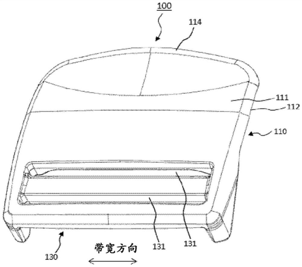
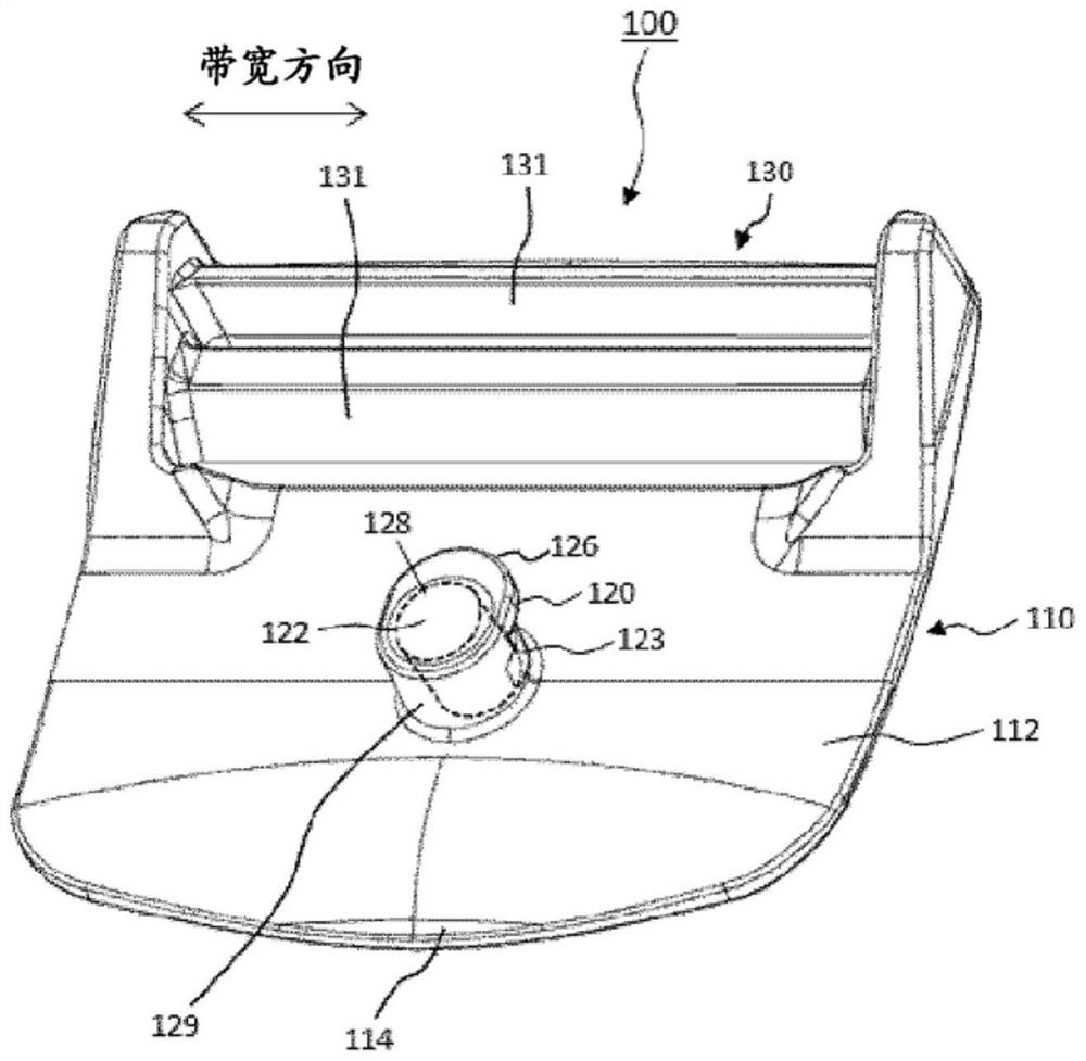
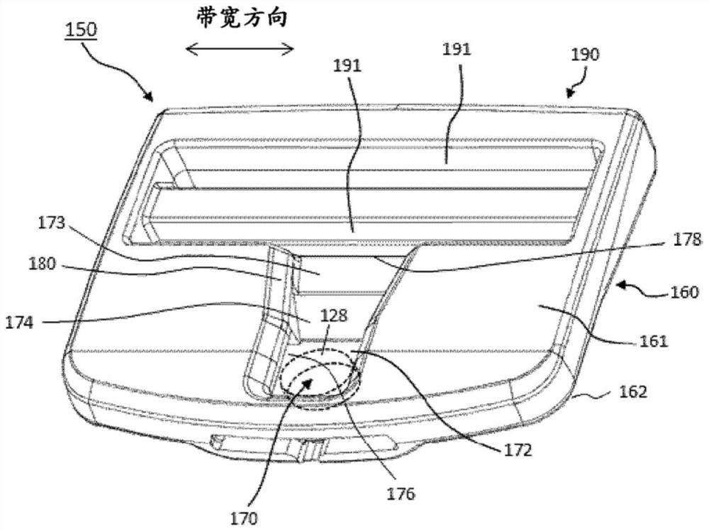
[0052] Picture 1-1 is a perspective view of the male part (100) of the buckle (10) according to the first embodiment of the present invention viewed from the surface (111) side. Figure 1-2 is a perspective view of the male part (100) of the buckle (10) according to the first embodiment of the present invention as viewed from the rear (112) side. diagram 2-1 is a perspective view of the female part (150) of the buckle (10) according to the first embodiment of the present invention viewed from the surface (161) side. Figure 2-2 is a perspective view of the female part (150) of the buckle (10) according to the first embodiment of the present invention viewed from the back side (162). image 3 is a perspective view when the male part (100) and the female part (150) of the buckle (10) according to the first embodiment of the present invention are engaged.

[0053] (1-1. Overall structure)

[0054] The male part (100) of the buckle (10) of this embodiment includes: a first pla...

no. 2 approach >

[0091] Figure 5 is a perspective view of the male part (100) of the buckle according to the second embodiment of the present invention viewed from the back side. Figure 6 is a perspective view of the female part (150) of the buckle according to the second embodiment of the present invention viewed from the surface side. exist Figure 5 and Figure 6 Herein, constituent elements denoted by the same reference numerals as those of the first embodiment denote the same constituent elements as those of the first embodiment, and detailed description thereof will be omitted. Hereinafter, differences between the second embodiment and the first embodiment will be described.

[0092]In the buckle (10) of this embodiment, the protruding portion (120) has a top surface (122) and a slope (124) connected to the top surface (122) and descending toward the opposite side of the first belt mounting portion (130). ). Like the slope (174) of the recessed portion (170) described in the first...

no. 3 approach >

[0099] Figure 7 is a perspective view of the buckle female part (150) according to the third embodiment of the present invention as viewed from the surface side. Figure 7 In the description, the constituent elements denoted by the same reference numerals as those of the first embodiment denote the same constituent elements as those of the first embodiment, and detailed description thereof will be omitted. In addition, since the male part (100) of the buckle of 3rd Embodiment is the same as 1st Embodiment, the description is abbreviate|omitted.

[0100] The female part (150) of the third embodiment does not have slopes (124, 174), which is different from the female part of the second embodiment in this aspect, and other structures are the same as the female part of the second embodiment. In the buckle female part (150) of the third embodiment, at the end of the first bottom surface (172) on the side of the second belt mounting portion (190), instead of the slope (174), a (1...


PUM


Abstract

Provided is a buckle with improved freedom of attachment and detachment operations. This buckle is provided with a male member having a projecting portion, and a female member having a recessed portion capable of engaging with the male member, wherein: the female member has an inclined surface which links a top surface of a second plate-shaped base portion and the recessed portion to guide the projecting portion toward the recessed portion; the projecting portion has a claw portion; the recessed portion has a claw receiving portion capable of engaging with the claw portion; the outline of theclaw receiving portion that is visually recognized when the female member is seen from the top surface side is a polygonal line shape or a curved line shape which extends out toward the opposite sideto a second belt fitting portion; a magnet is embedded in one of the projecting portion and the recessed portion; and a magnet of which the magnetic poles are oriented in such a way as to be attractedby the magnet, or a metal attracted by the magnet, is embedded in the other.

Description

technical field [0001] The present invention relates to a buckle using a magnet. Background technique [0002] In the past, not only the waist belt, but also the ends of the belts attached to various items such as bags, backpacks, clothes, shoes, helmets, sporting goods, and packaging utensils, were used to make the male part and the female part free to attach and detach. Snap-on buckle. In such a buckle, on the one hand, it is required to be easy to attach and detach, and on the other hand, it is required to prevent unintentional detachment. Conventionally, various buckle structures have been proposed in order to satisfy such required characteristics. [0003] In Japanese Unexamined Publication No. 62-119815 (Patent Document 1), a buckle is described, which is composed of a first connecting member and a second connecting member capable of engaging and detaching from the first connecting member, and The rear end of the first connecting member and the second connecting mem...

Claims


Application Information

Patent Timeline
Patent Type & Authority Applications(China)
IPC IPC(8): A44B11/25
CPCA44B11/258A44B11/25
Inventor 伊藤直幸金子仁
Owner YKK CORP
Why Eureka
Try Eureka