
Camera component, camera component control method, and electronic device

A technology of camera components and electronic equipment, which is applied in the electronic field and can solve problems such as different picture effects, restrictions on the screen ratio of mobile phones, and high cost of mobile phones

Active Publication Date: 2021-08-20
BOE TECH GRP CO LTD
View PDF7 Cites 0 Cited by
  • Summary
  • Abstract
  • Description
  • Claims
  • Application Information

AI Technical Summary

Problems solved by technology

[0002] In related technologies, electronic devices such as mobile phones use at least two cameras to realize the front and back shooting functions of the mobile phone, which makes the cost of the mobile phone relatively high, and the front camera of the mobile phone usually needs to be set on the display screen of the mobile phone. The corresponding viewfinder limits the screen-to-body ratio of the mobile phone. At the same time, due to structural layout and other factors, the pixels of the front and back shots of the phone are inconsistent, which makes the picture effects of the front and back shots of the phone different, affecting the experience.

Method used


Image

  • Camera component, camera component control method, and electronic device
  • Camera component, camera component control method, and electronic device
  • Camera component, camera component control method, and electronic device

Examples


Embodiment Construction

[0068] Embodiments of the present invention are described in detail below, examples of which are shown in the drawings, wherein the same or similar reference numerals designate the same or similar elements or elements having the same or similar functions throughout. The embodiments described below by referring to the figures are exemplary only for explaining the present invention and should not be construed as limiting the present invention.

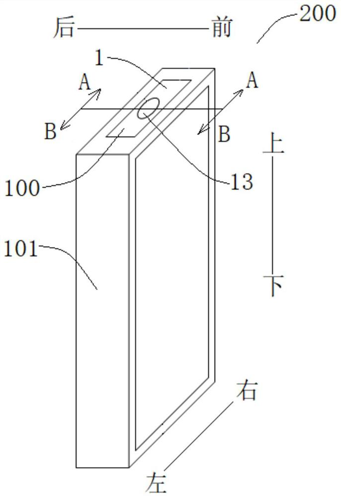
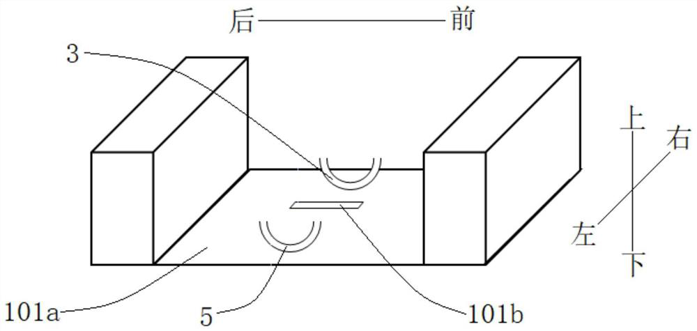
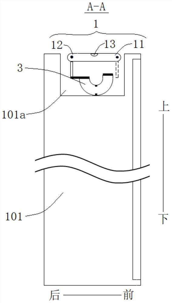
[0069] Refer below Figure 1-Figure 4 A camera assembly 100 according to an embodiment of the present invention is described.

[0070] Such as Figure 1-Figure 4 and Figure 12 As shown, the camera head assembly 100 according to the embodiment of the present invention includes a camera module 1 , a front axle device 2 and a forward turning drive device 3 .

[0071] The camera module 1 includes a front end 11, a rear end 12, and a lens 13 located at the top between the front end 11 and the rear end 12, and the front shaft device 2 incl...


PUM


Abstract

The invention discloses a camera assembly, a control method of the camera assembly, and electronic equipment. The camera assembly includes a camera module, a front axle device, and a forward-turning drive device. The camera module includes a front end, a rear end, and a front end and a rear end. For the lens at the top, the front shaft device includes a front shaft, which is adapted to pivotally cooperate with the front end. When the front shaft is pivotally matched with the front end, the front flip driving device can drive the camera module to pivot forward around the front shaft. Turn, so that the camera module is rotated to a forward-looking state in which the rear end is lifted and the lens faces forward to view the view. According to the camera assembly of the present invention, the shooting function of the electronic equipment is enriched, which is beneficial to reduce the cost and realize the full-screen display of the electronic equipment.

Description

technical field [0001] The present invention relates to the field of electronic technology, in particular to a camera assembly, a method for controlling the camera assembly, and electronic equipment. Background technique [0002] In related technologies, electronic devices such as mobile phones use at least two cameras to realize the front and back shooting functions of the mobile phone, which makes the cost of the mobile phone relatively high, and the front camera of the mobile phone usually needs to be set on the display screen of the mobile phone. The corresponding viewfinder limits the screen-to-body ratio of the mobile phone. At the same time, due to structural layout and other factors, the pixels of the front and back shots of the phone are inconsistent, which makes the picture effects of the front and back shots of the phone different, affecting the experience. Contents of the invention [0003] The present invention aims to solve at least one of the technical probl...

Claims


Application Information

Patent Timeline
Patent Type & Authority Patents(China)
IPC IPC(8): H04M1/02G06F1/16
CPCH04M1/0264H04M1/0266G06F1/1686G06F1/1637H04M2250/20G06F1/1626H04N23/50H04N23/57H04N23/695
Inventor 邹祥祥
Owner BOE TECH GRP CO LTD
Learn More