
Nail gun provided with wide and narrow nail switching and nail blocking structure

A technology of wide and narrow nails and nail stoppers, which is applied in the field of nail guns with wide and narrow nail switching and nail stop structures, can solve the problems of failure to stop nails, uncertainty of the distance of left and right movement, and poor quality of nails, etc., to improve Nail quality effects

Active Publication Date: 2020-10-13
HANGZHOU KELONG ELECTRICAL APPLIANCE TOOLS
View PDF8 Cites 1 Cited by
  • Summary
  • Abstract
  • Description
  • Claims
  • Application Information

AI Technical Summary

Problems solved by technology

However, existing nail guns need to use a nail gun with wide nails when using wide nails, and a nail gun with narrow nails when using narrow nails. The user needs to match the inconvenient factors caused by the width of the nails. Feet tend to be skewed, resulting in poor quality nails
[0003] The invention patent with the authorized notification number CN 102785223B discloses a nail guide structure and a nail gun including the nail guide structure. This structure can solve the problem that the nail foot is easily skewed when nailing to a certain extent.
However, under the action of the elastic member, the supporting member used in it moves horizontally along the positioning groove of the guide plate, and the distance of the left and right movement is uncertain, which may not be able to play the role of retaining the nail, and there is still a skewed nail foot during the nailing process. , The nail feet are skewed or stuck after the nailing is completed

Method used


Image

  • Nail gun provided with wide and narrow nail switching and nail blocking structure
  • Nail gun provided with wide and narrow nail switching and nail blocking structure
  • Nail gun provided with wide and narrow nail switching and nail blocking structure

Examples


Embodiment

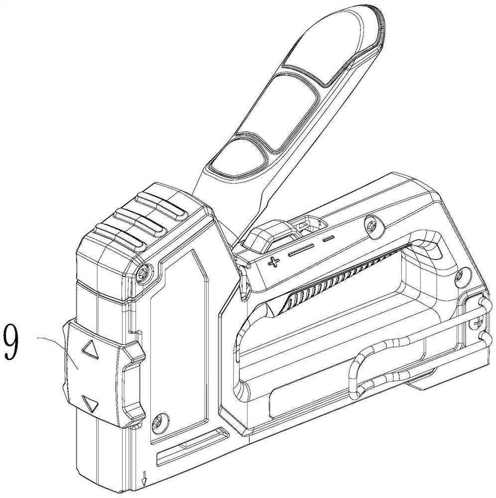
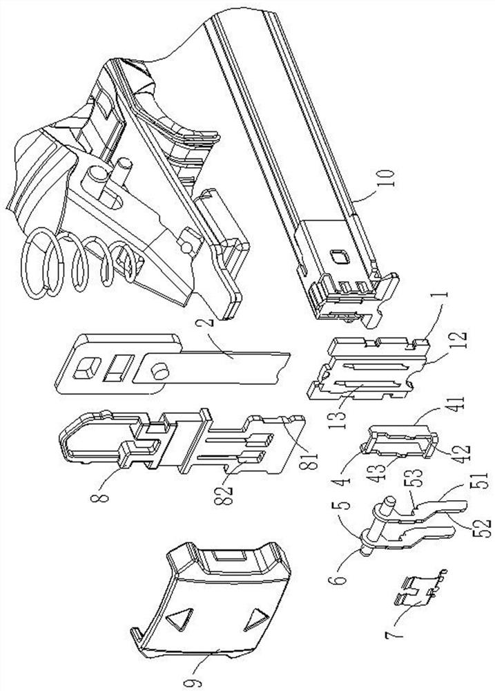
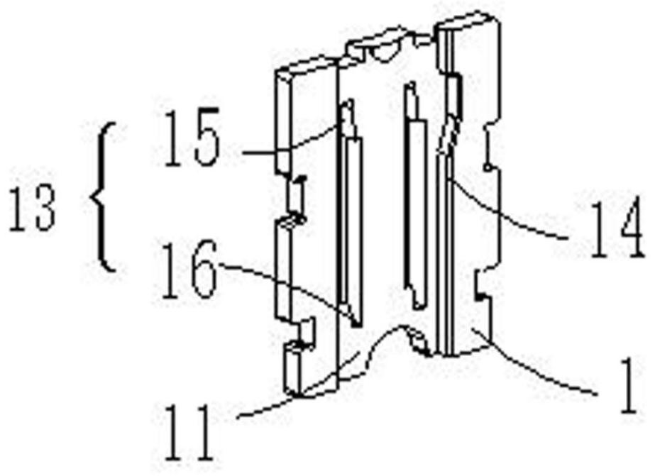
[0020] Example: as attached Figure 1~4 As shown, the present invention provides a nail gun with a wide and narrow nail switch and a nail retaining structure, which is arranged in a nail gun with a nail rail 10, and includes a punching guide rail 1 that is vertically arranged in front of the nail rail 10. The punching guide rail 1 It has a first surface 11 and a second surface 12 opposite to the first surface 11, the first surface 11 of the punching guide rail 1 faces the nail rail 10, and the punching guide rail 1 is provided with the first surface 11 and the second The positioning groove 13 on the surface 12, a guide groove 14 extending longitudinally is also provided on the first surface 11, for the punching sheet 2 arranged on the punching sheet guide rail 1 and / or the nails 3 arranged in the nail rail 10 to guide along the The guide groove 14 slides in a straight line, and one side of the positioning groove 13 extends upwards to form a groove A15 for slidingly setting the...


PUM


Abstract

The invention discloses a nail gun provided with a wide and narrow nail switching and nail blocking structure, and relates to the field of tools. The structure is arranged in the nail gun provided with a nail rail. The nail gun comprises a punching guide rail vertically arranged before the nail rail. The punching guide rail is provided with a locating groove. One side of the locating groove extends upwards to form a groove A and is provided with an adjusting block in a sliding manner. The other side of the locating groove extends downwards to form a groove B and is provided with nail blockingbars in a rotating manner through a pin shaft. The nail blocking bars can rotate around the pin shaft between the initial position and the ending position. A spring sheet abuts against the nail blocking bars, and thus the nail blocking bars have a tendency to resetting to the initial position at any time. A switching pull knob is vertically arranged before the adjusting block and used for selectively abutting against the adjusting block, and thus the adjusting block cannot be moved to a second position. According to the nail gun, by changing the position of the switching pull knob, the nail output gap is changed, thus wide and narrow nails can be used on the same nail gun, meanwhile, two nail blocking bars are installed in the punching guide groove, and thus the nailing quality of the widenails is improved.

Description

technical field [0001] The invention relates to the field of tools, in particular to a nail gun with a structure for switching between wide and narrow nails and a nail retaining structure. Background technique [0002] Nail gun, also known as nail gun, is often called a nail gun because its shape and principle are similar to a pistol. In the European and American nail gun markets, nail guns are not only professional tools, but also suitable for simple decoration and decoration by ordinary families and individuals. However, the existing nail guns need to use a nail gun with wide nails when using wide nails, and use a nail gun with narrow nails when using narrow nails. The user needs to match the nail width to bring inconvenience. Feet tend to be skewed, resulting in poor quality nails. [0003] The invention patent with the authorized notification number of CN 102785223B discloses a nail guide structure and a nail gun including the nail guide structure. This structure can s...

Claims


Application Information

Patent Timeline
Patent Type & Authority Applications(China)
IPC IPC(8): B25C5/00B25F5/00
CPCB25C5/00B25F5/00
Inventor 严国民康小明
Owner HANGZHOU KELONG ELECTRICAL APPLIANCE TOOLS
Learn More