
Multi-row gun nail clip capable of preventing nails from being stuck

A technology of magazine clips and gun nails, applied in the field of gun nails, can solve the problems of increasing the labor intensity of workers, the nail bars cannot be firmly limited, and the bottom row nail bars cannot be pushed, etc., so as to improve the working efficiency of nailing, the structure is ingenious, and the The effect of preventing jamming

Pending Publication Date: 2020-11-10
谢新杰
View PDF0 Cites 0 Cited by
  • Summary
  • Abstract
  • Description
  • Claims
  • Application Information

AI Technical Summary

Problems solved by technology

The clip of the gun nail is mainly used for nailing strips, and one or more rows of nail strips are installed inside. The fixing of the nail strips in the existing magazine mainly depends on the spring. When installing multiple rows of nail strips, it is easy to break due to excessive spring pressure The bottom row of nail strips cannot be pushed, and the spring pressure is too low, so the nail strips cannot be firmly limited in the magazine. In addition, the existing nail guns are easy to get stuck when they are working. When the nails are stuck, the gun head needs to be removed before repairing, which is troublesome to maintain. , while increasing the labor intensity of workers and reducing work efficiency

Method used


Image

  • Multi-row gun nail clip capable of preventing nails from being stuck
  • Multi-row gun nail clip capable of preventing nails from being stuck
  • Multi-row gun nail clip capable of preventing nails from being stuck

Examples


Embodiment Construction

[0031] The present invention will be described in detail below in conjunction with the accompanying drawings and specific embodiments.

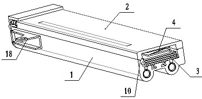
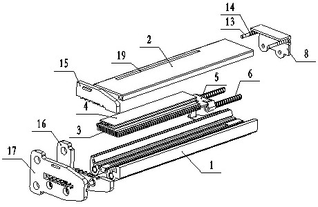
[0032] see Figure 1 to Figure 6 A multi-row nail clip for anti-stabbing, including a fixed clip 1, characterized in that: the fixed clip 1 is provided with a chamber for placing a nail strip 3, and the left side of the chamber 1-5 The slope parallel to the right side 1-6 forms an angle with the bottom surface 1-7 of the chamber. The bottom of the fixed magazine 1 is provided with two circular guide grooves 1-1, and the guide groove 1-1 is provided with There is an opening 1-2, and the opening 1-2 communicates with the chamber for fixing the clip 1; multiple rows of nail strips 3 are installed in the chamber, and springs 6 and nail pushing pieces are installed in the guide groove 1-1 5. The spring 6 can push the nail pusher 5 to push the nail strip 3 out of the nail outlet; the middle part of the fixed clip 1 is provided with a through groov...


PUM


Abstract

The invention relates to a multi-row gun nail clip capable of preventing nails from being stuck. The multi-row gun nail clip capable of preventing the nails from being stuck comprises a fixed clip body, wherein the fixed clip body is provided with a cavity used for placing nail strips; two circular guide grooves are formed in the bottom of the fixed clip body; the multiple rows of nail strips areinstalled in the cavity; springs and a nail pushing piece are installed in the guide grooves; the springs can push the nail pushing piece to push the nail strips out towards a nail outlet; a through groove is formed in the middle of the fixed clip body; a shifting handle is installed on the nail pushing piece and is moved to enable the nail pushing piece to draw back so as to realize the clampingof the nail strips; magnet holes are formed in the fixed clip body; and magnets are installed on the magnet holes and can adsorb the nail strips onto the bottom face of the cavity. According to the multi-row gun nail clip capable of preventing the nails from being stuck provided by the invention, the multiple rows of nail strips can be installed at a time and can be automatically replaced for nailing, so that the nailing work efficiency is improved, and the labor intensity is reduced; and the magnets are arranged on the fixed clip body, the nail strips are attached to the bottom face of the cavity under the action of the magnets and the auxiliary spring pieces, and nail heads fall into a spigot groove, so that the positions of the nail strips are more accurate in the moving process, and the nails are prevented from being stuck.

Description

technical field [0001] The invention relates to the technical field of nail guns, in particular to a multi-row nail gun magazine for preventing nail jamming. Background technique [0002] Gun nails are widely used in the manufacture of woodworking furniture and house decoration. The magazine of gun nails is the core component of gun nails, which directly determines the performance and work efficiency of gun nails. The clip of the gun nail is mainly used for nailing strips, and one or more rows of nail strips are installed inside. The fixing of the nail strips in the existing magazine mainly depends on the spring. When installing multiple rows of nail strips, it is easy to break due to excessive spring pressure The bottom row of nail strips cannot be pushed, and the spring pressure is too low, so the nail strips cannot be firmly limited in the magazine. In addition, the existing nail guns are easy to get stuck when they are working. When the nails are stuck, the gun head need...

Claims


Application Information

Patent Timeline
Patent Type & Authority Applications(China)
IPC IPC(8): B25C3/00B25C7/00
CPCB25C3/00B25C7/00
Inventor 谢新杰
Owner 谢新杰
Learn More