Laser detection device

A technology of laser detection and laser rangefinder, which is applied in the field of detectors, can solve problems such as placement deviation, and achieve the effects of stable support, improved stability, and convenient operation

Active Publication Date: 2020-10-30
WENZHOU UNIVERSITY
View PDF6 Cites 0 Cited by
  • Summary
  • Abstract
  • Description
  • Claims
  • Application Information

AI Technical Summary

Problems solved by technology

[0004] The purpose of the present invention is the laser detection device, to solve the technical problem of wiping the lens of the laser detection device and causing the placement position to deviate

Method used


Image

  • Laser detection device
  • Laser detection device

Examples


Embodiment 1

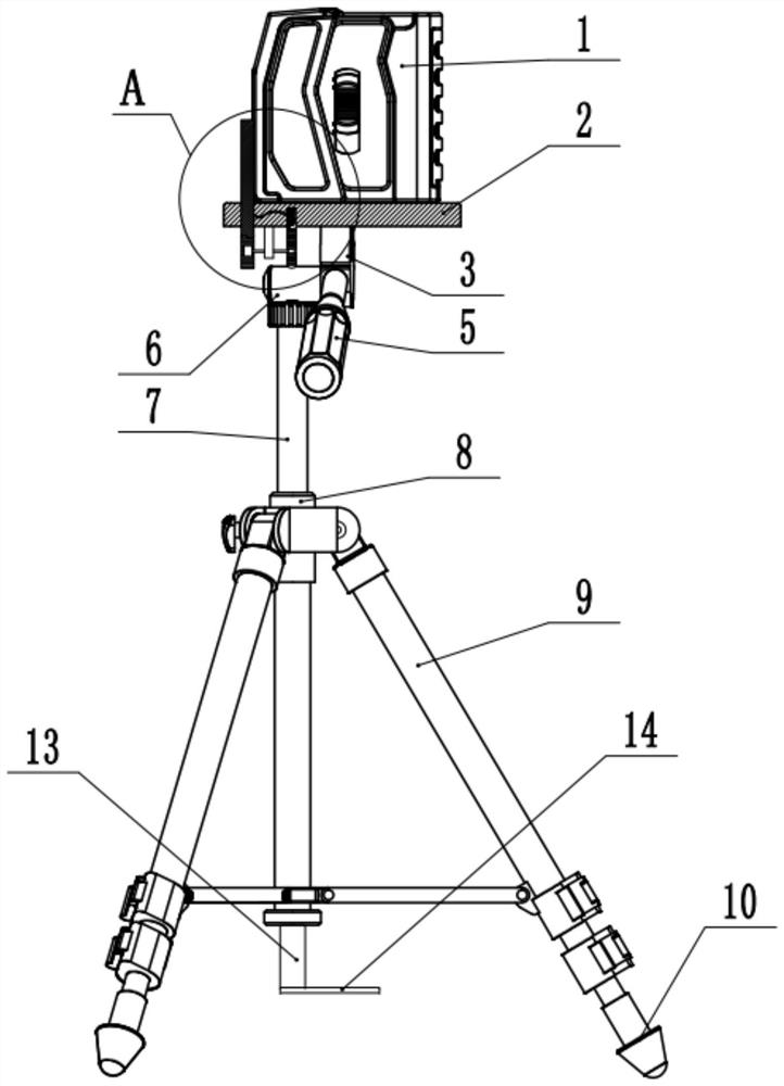
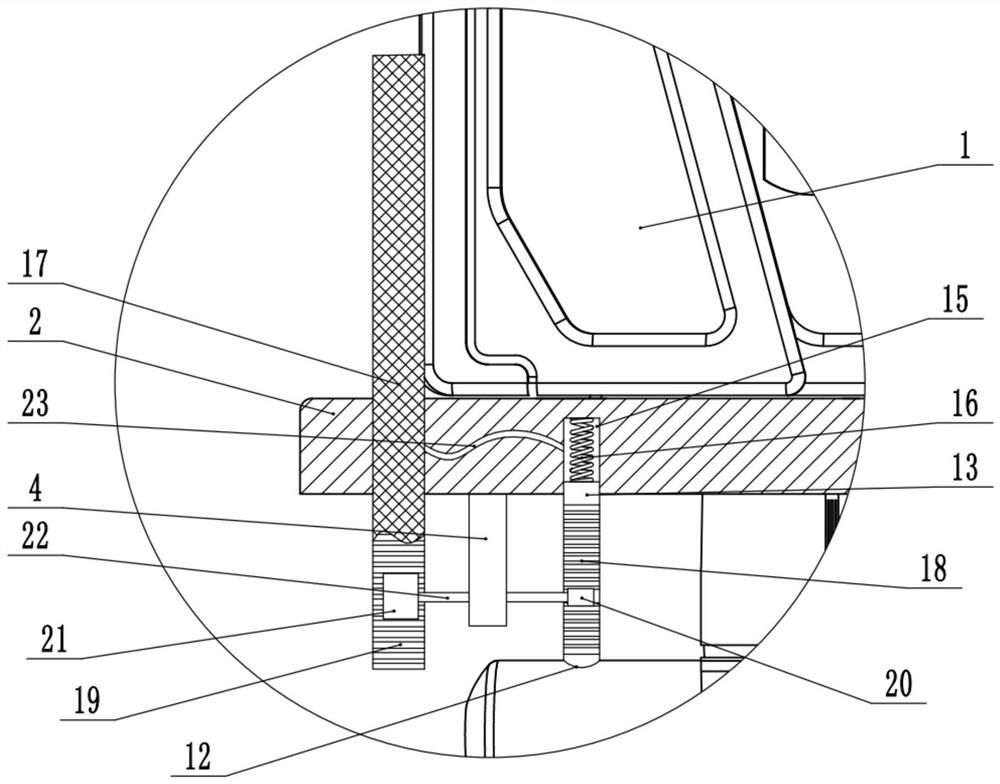
[0031] as attached figure 1 with attached figure 2 As shown, the laser detection device includes a laser range finder 1, and the bottom of the laser range finder 1 is threadedly connected with a support mechanism. The support mechanism includes a support base 2 , and the laser range finder 1 is screwed and fixedly connected to the top surface of the support base 2 . The bottom of the support base 2 is hinged with a steering head 3 . A shaft rod 6 is welded and fixed on the bottom of the steering head 3, and the axial direction of the shaft rod 6 is perpendicular to the horizontal plane. A sleeve 7 is sheathed on the outside of the shaft 6 , and the sleeve 7 slides freely relative to the shaft 6 , and a positioning ring 8 for fixing the sleeve 7 is fixed on the top of the sleeve 7 . The outer wall of the pipe sleeve 7 is also welded and fixed with a connecting sleeve 9, and the outer wall of the connecting sleeve 9 is respectively hinged with three legs 10, and the angle be...


PUM


Abstract

The invention belongs to the technical field of detectors, and particularly discloses a laser detection device. The laser detection device comprises a cylinder, wherein the two ends of the cylinder are provided with an objective lens and an eyepiece respectively, a baffle used for shielding the objective lens is hinged to the side wall of the objective lens, a torsional spring is hinged to the joint of the baffle, the baffle shields the objective lens when the torsional spring is in the free state, a slide cavity is vertically formed in the cylinder, a slide block is slidably connected into the slide cavity, a triggering block is horizontally and slidably connected to the side wall of the slide cavity, a cavity communicating with the outside is formed in the adjacent side of the slide cavity, a transmission block is vertically and slidably connected to the inner wall of the cavity, a connecting rod is hinged between the transmission block and the triggering block, and a limiting blockmatched with transmission block is fixedly connected to the side wall of the baffle, and can freely slide in the cavity. The laser detection device mainly aims at solving the technical problem that the objective lens of the detector cannot be protected in casing of falling.

Description

technical field [0001] The invention belongs to the technical field of detectors, and specifically discloses a laser detection device. Background technique [0002] The laser detection device is an instrument that uses a certain parameter of the modulated laser to realize the distance measurement to the target. A batch of new miniature rangefinders with the advantages of fast ranging, small size and reliable performance have emerged at home and abroad, which can be widely used in industrial measurement and control, mines, ports and other fields. At present, there is often a lot of dust on the construction site, and the lens of the laser rangefinder is easily covered by dust, resulting in inaccurate distance measurement results. [0003] At present, for the above problems, the common solution in the prior art is to use a cleaning cloth to frequently wipe the instrument to ensure the measurement requirements. Although this method can solve the problem of cleaning, it is nece...

Claims


Application Information

Patent Timeline
Patent Type & Authority Applications(China)
IPC IPC(8): B08B1/00G01S7/481
CPCB08B1/006B08B1/008G01S7/481
Inventor 谢晓文
Owner WENZHOU UNIVERSITY
Why Eureka
Try Eureka