
Method of cutting square grooves in building walls or floors

A technology for building walls and floors, which is applied in the field of opening square grooves on building walls or floors, and can solve problems such as mismatched size design of square grooves, damage to walls or floors, and low efficiency of square grooves

Active Publication Date: 2022-05-03
山东城邦建设有限公司
View PDF0 Cites 0 Cited by
  • Summary
  • Abstract
  • Description
  • Claims
  • Application Information

AI Technical Summary

Problems solved by technology

[0003] The purpose of the present invention is to overcome the deficiencies of the prior art, to provide a method for opening square grooves on the building wall or floor, to solve the problem that there is no special tool for opening square grooves on the wall or floor, and the efficiency of manually opening square grooves is low. It is easy to cause damage to the wall or floor, and the size of the square groove often does not match the design

Method used


Image

  • Method of cutting square grooves in building walls or floors
  • Method of cutting square grooves in building walls or floors
  • Method of cutting square grooves in building walls or floors

Examples


Embodiment 1

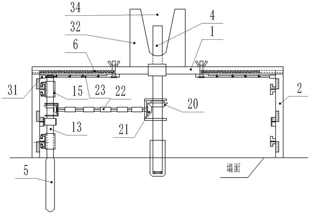
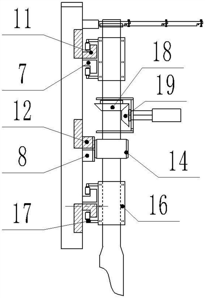
[0047] like Figure 1-14 Shown, the present invention opens the method for square groove on building wall or floor, comprises steps:

[0048] Step 1. Set the positioning top frame 1. A central positioning shaft 4 is inserted in the center of the positioning top frame 1. The four sides of the positioning top frame 1 are respectively connected with sliding side frames 2, and between the positioning top frame 1 and the sliding side A tension spring 6 is connected between the plate frames 2, and two opposite L-shaped side plate guide rails 7 and a side plate bar tooth 8 are arranged on the inner surface of the sliding side plate frame 2. On the L-shaped side plate guide rail 7 and the side Side plate chute 9 is provided on the sliding side plate frame 2 on one side of the slat teeth 8;

[0049] Step 2. Set up the right-angle plate connecting frame 3. On the two connecting end surfaces of the right-angle plate connecting frame 3 and the side plate chute 9 on the sliding side plate...

Embodiment 2

[0067] like Figure 1-14 Shown, the present invention opens the method for square groove on building wall or floor, on the basis of embodiment 1, is provided with positioning ruler 23 on the corresponding position of each sliding side plate frame 2 on positioning roof frame 1, described The positioning ruler 23 includes an installation positioning block 24 and a chi section 25, the multi-section chi section 25 is connected end to end, and the end chi section 25 is connected to the installation positioning block 24, and the installation positioning block 24 is installed on the positioning roof frame 1 by adjusting bolts;

[0068] The connecting head of the chi section 25 is provided with a step platform, and the butt ends of the two connected chi sections 25 are connected by a pin bar 26, and one end of the pin bar 26 is provided with an extruding spring 27, and the two parts are connected by the extruding spring 27. The ends of the terraces connecting the length sections 25 are ...

Embodiment 3

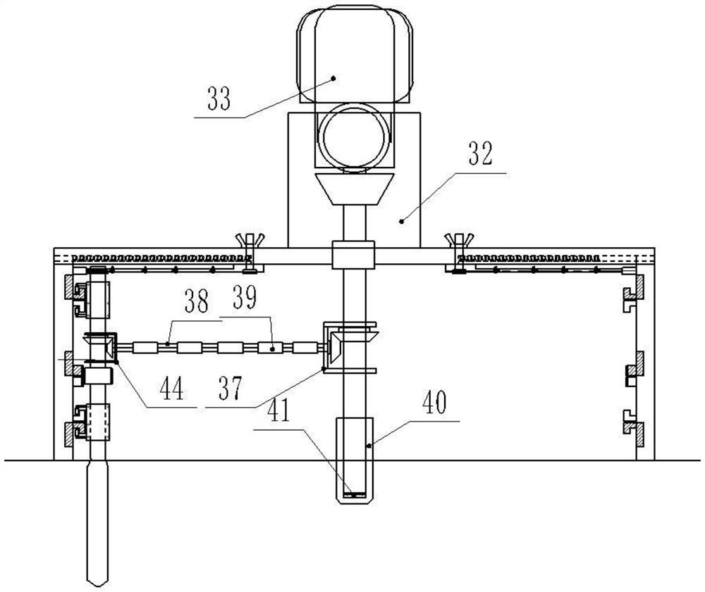
[0075] like Figure 1-14 As shown, in the method for opening square grooves on building walls or floors in the present invention, on the basis of the above-mentioned embodiments, a limit plate 32 is provided on the side of the center positioning shaft 4 installed on the positioning roof frame 1, and the limit plate 32 is arranged on the side of the position limit The plate 32 is provided with a clamping opening 34 for clamping the electric drill 33 .

[0076] Hand drill 33 adopts attached Figure 13 As shown in the electric drill with a horizontal handle, when installing, the upper end of the center positioning shaft 4 is clamped on the hand electric drill 33, and the horizontal handle of the hand electric drill 33 is stuck in the clamping opening 34 of the limiting plate 32 to prevent the positioning of the top plate The position of rack 1 is offset.


PUM


Abstract

The invention discloses a method for cutting a square groove on a building wall or floor. A square groove position line is drawn on the wall or floor, a positioning hole is drilled in the center of the square groove position line, and then the inner edge of the square groove position line is drilled. Drill a slotted hole, adjust the sliding side plate frame, align the frame formed by the sliding side plate frame and the right-angle plate connector with the size of the square slot, lock the positioning ruler, move the slot milling drill and align the position of the slot milling hole, and center the positioning axis The upper end of the shaft head is clamped on the hand drill; insert the milling drill into the milling hole, insert the inner end of the central positioning shaft into the positioning hole, press the hand drill to the wall or floor, start the hand drill, The slot milling drill continuously mills the back-shaped slot on the wall or floor, remove the square slot milling equipment, and knock out the remaining bosses in the square slot. The invention solves the problems that there is no special tool for opening the square groove on the wall or the floor, the efficiency of manually opening the square groove is low, the wall or the floor is easy to be damaged, and the size of the opened square groove often does not match the design.

Description

technical field [0001] The invention relates to the field of building decoration tool equipment and technology, in particular to a method for opening a square groove on a building wall or floor. Background technique [0002] In the process of house decoration, it is often necessary to open square grooves on the wall or floor to install various control boards or plug-in boards. Since the wall is mainly made of bricks or concrete, the floor is mostly made of concrete. The material is relatively hard. If it is necessary to open a square groove on the wall or floor during decoration, there is no special equipment for opening a square groove in the prior art. Generally, workers use saw blades to cut a well on the wall or floor. T-shaped groove, and then use tools to dig out the bricks or concrete in the square groove to form a square groove. This method of opening a square groove is inefficient. Using a saw blade to cut a well-shaped groove will cause damage to the wall structure...

Claims


Application Information

Patent Timeline
Patent Type & Authority Patents(China)
IPC IPC(8): B28D1/14B28D1/18B28D7/00
CPCB28D1/14B28D1/18B28D7/005B28D7/00
Inventor 陈和东
Owner 山东城邦建设有限公司
Learn More