Thin film fluoropolymer composite cmp polishing pad
A fluoropolymer, composite polishing technology, used in electrical components, grinding tools, circuits, etc., can solve the problem of neglecting pad polymer modification
- Summary
- Abstract
- Description
- Claims
- Application Information
AI Technical Summary
Problems solved by technology
Method used
Image

Examples
example 1
[0075] The physical properties of a set of samples A were performed with and without the addition of 10 weight percent PTFE-1 and PFA. Notable changes, as shown in the table below, are reductions in tensile strength, hardness, and most mechanical properties. Of particular interest is the difference between the effect of addition on the shear storage modulus (G'), which is characteristic of elastic behavior, and the effect on the shear loss modulus (G"), which represents Energy dissipated in the sample. The shear storage modulus G' at 40°C is significantly lower (-31% for PFA and -45% for PTFE) relative to the control. The shear loss modulus G" is shown Similar trends were observed (-26% for PFA and -37% for PTFE). While all samples were primarily elastomeric polymers, PFA and PTFE additions increased tan δ (the ratio of G” to G’) by 6% and 14%, respectively. This is a direct measure of the increase in energy dissipation caused by fluoropolymer addition. Similar trends were o...
example 2
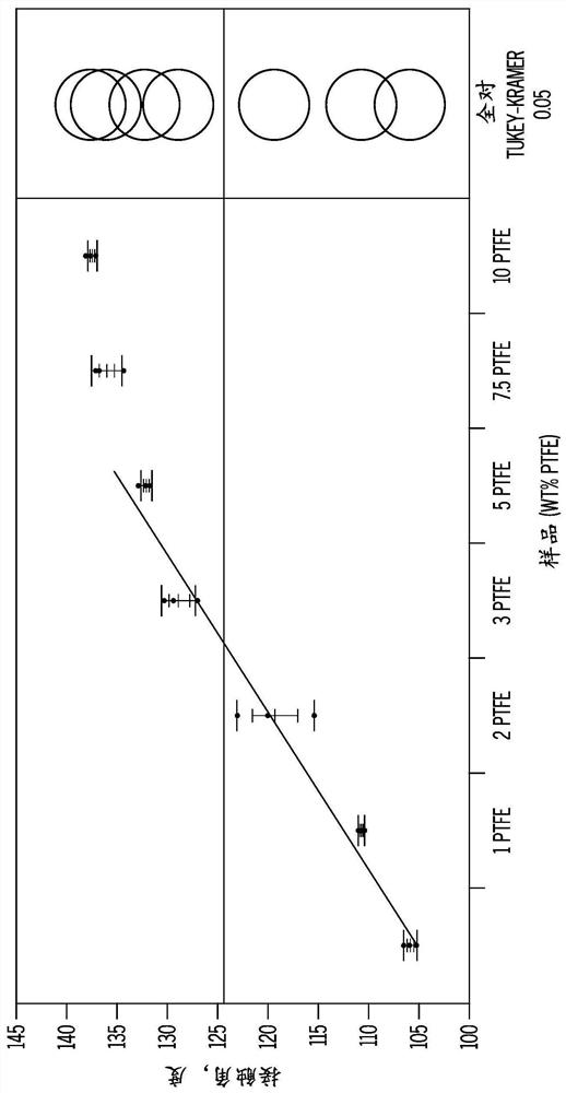
[0081] The deionized water contact angles were measured on Sample B, a set of mesoporous polyurethane pads that had different amounts of PTFE-2 added during the manufacturing process. Such as figure 1 As shown, the contact angle increases directly with increasing PTFE content, reaching a steady state value of about 140 degrees (PTFE content is 7.5%). Clearly, all mats with both PTFE and PFA additions are more hydrophobic than the parent mat. Nevertheless, the polished surface was hydrophilic as measured at a surface roughness of 10 μm rms with distilled water at pH 7 after soaking in distilled water for 5 minutes.
example 3
[0083] To demonstrate the beneficial effects of the present invention, polishing tests were performed on a set of high strength Sample A pads with and without PTFE and PFA additions. The concentration of each added fluoropolymer was 8.1%. In each test on an Applied Mirra CMP polishing tool, three slurries were tested on each pad set using a 60 200 mm TEOS monitor wafer. The slurries used were two ceria slurries (Asahi CES333F2.5 and DA Nano STI2100F) and fumed silica slurries (CabotSS25). The conditions used were 3 psi (20.7 kPa) downforce, 93 rpm platen speed, 87 rpm carriage speed and a slurry flow rate of 150 ml / min. Finishers vary by slurry type. For the ceria slurry, a Saesol LPX-C4 diamond conditioner disc was used. For silica slurries, Saesol AK45 conditioner discs were used. All dressers were used with a polishing condition of 7 lbf (3.2 kgf). For each run, a 20-minute pad break-in conditioning step was performed at 7 lbf (3.2 kgf) to ensure a uniform initial pad ...
PUM
| Property | Measurement | Unit |
|---|---|---|
| density | aaaaa | aaaaa |
| thickness | aaaaa | aaaaa |
| thickness | aaaaa | aaaaa |
Abstract
Description
Claims
Application Information
 - R&D
- Intellectual Property
- Life Sciences
- Materials
- Tech Scout
- Unparalleled Data Quality
- Higher Quality Content
- 60% Fewer Hallucinations
Browse by: Latest US Patents, China's latest patents, Technical Efficacy Thesaurus, Application Domain, Technology Topic, Popular Technical Reports.
© 2025 PatSnap. All rights reserved.Legal|Privacy policy|Modern Slavery Act Transparency Statement|Sitemap|About US| Contact US: help@patsnap.com