Supercharge Your Innovation With Domain-Expert AI Agents!

Variable radial fluid device with counteracting cams

A cam, fluid technology, used in pump devices, safety devices, variable displacement engines, etc.

Active Publication Date: 2014-01-15
BELL HELICOPTER TEXTRON INC
View PDF5 Cites 11 Cited by
  • Summary
  • Abstract
  • Description
  • Claims
  • Application Information

AI Technical Summary

Problems solved by technology

However, changing valve timing may require more energy to open and close each valve

Method used


Image

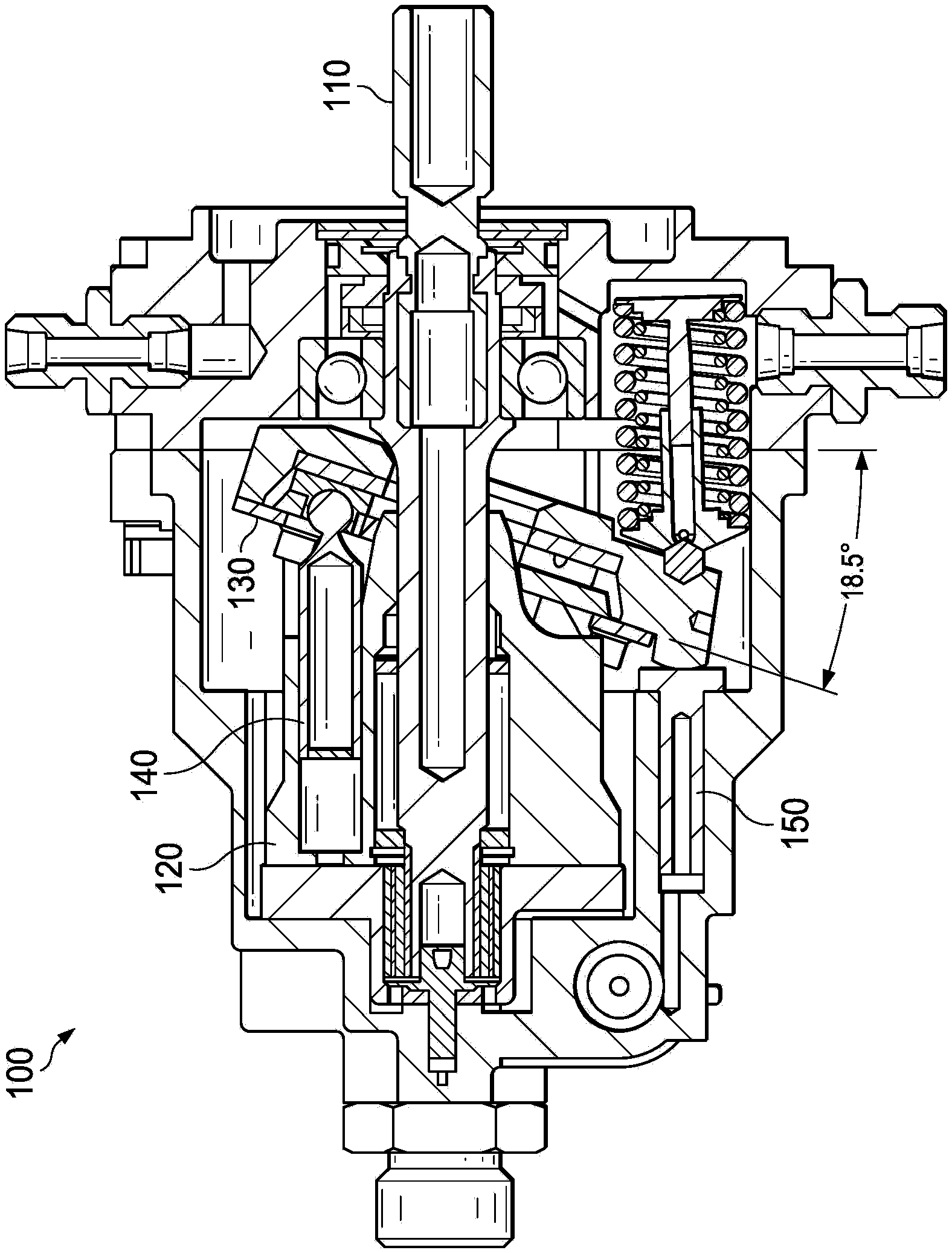
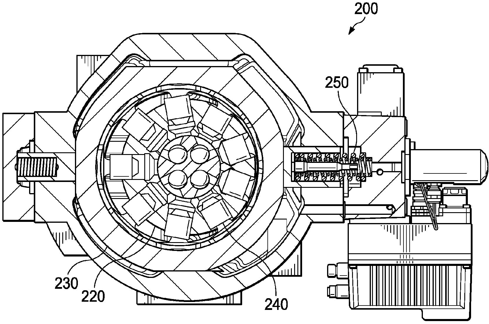
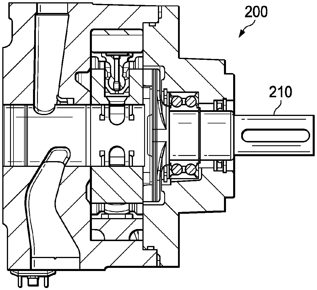
  • Variable radial fluid device with counteracting cams
  • Variable radial fluid device with counteracting cams
  • Variable radial fluid device with counteracting cams

Examples


Embodiment Construction

[0023] As explained above, the flow of fluid in a fluid device can be varied by varying the stroke displacement distance of the piston or the valve timing. However, changing the displacement distance of the piston stroke requires a lot of energy to move the cam to change the displacement distance. Likewise, varying the valve timing requires a significant amount of energy to open and close the valve when hydraulic flow is at its maximum.

[0024] Teachings of certain embodiments recognize the ability to adjust fluid flow in a fluid device without changing the displacement distance of the piston stroke or valve timing. Teachings of certain embodiments also recognize the ability to adjust fluid flow using very little energy compared to changing the displacement distance of a piston stroke or valve timing.

[0025] Figures 3A-3F is a radial fluid device 300 according to an exemplary embodiment. Figure 3A A front view of a radial fluid device 300 is shown, Figure 3B A side vi...


PUM


Abstract

According to one embodiment, a radial fluid device comprises a cylinder block, a first plurality of pistons, a second plurality of pistons, a first cam, a second cam, and a cam rotation device. Each of the first plurality of pistons is slidably received within a different one of a first plurality of radially extending cylinders. Each of the second plurality of pistons is slidably received within a different one of a second plurality of radially extending cylinders. The first cam is disposed about the first plurality of radially extending cylinders. The second cam is disposed about the second plurality of radially extending cylinders. The cam rotation device is coupled to the first cam and the second cam. The cam rotation device is operable to rotate the first cam in a first direction and the second cam in a second direction.

Description

technical field [0001] This invention relates generally to radial fluid devices, and more particularly to variable radial fluid devices with reaction cams. Background technique [0002] The subject matter discussed in this Background section should not be assumed to be prior art merely because it is mentioned in the Background section. Likewise, issues mentioned in the background section or issues related to the subject matter of the background section should not be assumed to have been previously recognized in the prior art. The Background section may rely on hindsight and may describe subject matter in ways not previously recognized in the prior art, and it should not be assumed that such descriptions represented the understanding or motives of those of ordinary skill in the art prior to the filing of this application. The subject matter of the background section merely represents different approaches, which may also be inventions in or in themselves. [0003] A fluidic ...

Claims


Application Information

Patent Timeline
Patent Type & Authority Applications(China)
IPC IPC(8): F01B1/06F01B25/02F03C1/04F03C1/40F04B1/04F04B1/07F04B27/04F04B27/073
CPCF04B9/042F04B19/02F04B23/06F04B49/005F04B49/16F04B1/066
Inventor 卡洛斯·A·费尼詹姆斯·E·索贝尔
Owner BELL HELICOPTER TEXTRON INC
Features
  • R&D
  • Intellectual Property
  • Life Sciences
  • Materials
  • Tech Scout
  • Unparalleled Data Quality
  • Higher Quality Content
  • 60% Fewer Hallucinations
Learn More