Temporary light soil retaining structure for side slope and construction method

A soil retaining structure and temporary technology, which is applied in the direction of foundation structure engineering, underwater structures, excavation, etc., can solve the problems of large force on the retaining plate, breakage of the support rod, and inconvenient construction, so as to achieve firm and stable force, and The effect of uniform force and convenient construction

Pending Publication Date: 2021-02-05
HUNAN UNIV OF SCI & TECH +1
View PDF0 Cites 2 Cited by
  • Summary
  • Abstract
  • Description
  • Claims
  • Application Information

AI Technical Summary

Problems solved by technology

[0002] There is a kind of side slope in the project, there is the possibility of local shallow landslides but no risk of deep landslides, and local shallow landslides have no impact on the completed project itself, so temporary slope retaining structures can only be built during the construction period, However, most of the existing soil retaining structures are fixed by installing struts on the rear side of the soil retaining board. The base of the soil plate is fixed. In this way, the soil retaining plate is still subjected to excessive force on the ground with relatively loose soil, and the fixed base will move backward accordingly, and the position of the soil retaining plate cannot be adjusted after the base is installed. The distance between the surfaces is not convenient for construction, and the poor drainage performance of the soil retaining board makes it bear too much weight and cause the brace to break

Method used


Image

  • Temporary light soil retaining structure for side slope and construction method
  • Temporary light soil retaining structure for side slope and construction method

Examples


Embodiment Construction

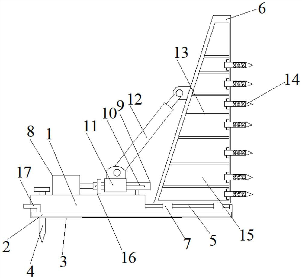
[0019] Below, in conjunction with accompanying drawing and specific embodiment, the invention is further described:

[0020] In the description of the present invention, it should be noted that the terms "top", "bottom", "one side", "another side", "front", "rear", "middle part", "inner", " The orientation or positional relationship indicated by "top", "bottom", etc. is based on the orientation or positional relationship shown in the drawings, which is only for the convenience of describing the present invention and simplifying the description, rather than indicating or implying that the referred device or element must have specific orientation, construction and operation in a specific orientation, and therefore should not be construed as limiting the invention; the terms "first", "second" and "third" are used for descriptive purposes only and should not be construed as indicating or implying relative Importance; In addition, unless otherwise clearly stipulated and limited, th...


PUM


Abstract

The invention discloses a temporary light soil retaining structure for side slope and a construction method, the side slope temporary light soil retaining structure comprises a fixing base, fixing rivets, a first sliding rod, a soil retaining plate, a hydraulic cylinder, a second sliding rod, a supporting rod and a drainage pipe, a concrete filling chamber is arranged in the bottom end of the fixing base, and a stainless steel wire mesh is installed at the bottom end of the concrete filling chamber. A pouring pipe communicated with the concrete filling chamber is arranged at one end of the fixing base, a first sliding rod is fixed to the position, close to the other end, of the fixing base, a first sliding sleeve is fixed to the bottom end of the soil retaining plate and slidably connectedwith the first sliding rod, the soil retaining plate is of a trapezoidal structure, and a hydraulic cylinder and a second sliding rod are fixed to the top of the fixing base. The second sliding rod is slidably sleeved with a push block. The push block is connected with the output end of the hydraulic cylinder, a second sliding sleeve is slidably connected to the second sliding rod, the top of thesecond sliding sleeve is hinged to one end of a supporting rod, the other end of the supporting rod is hinged to one side of a soil retaining plate, and a drainage pipe is installed on the other sideof the soil retaining plate. The breast board is firm in supporting and convenient to construct.

Description

technical field [0001] The invention relates to the technical field of slope retaining engineering construction, in particular to a temporary lightweight soil retaining structure for a slope and a construction method. Background technique [0002] There is a kind of side slope in the project, there is the possibility of local shallow landslides but no risk of deep landslides, and local shallow landslides have no impact on the completed project itself, so temporary slope retaining structures can only be built during the construction period, However, most of the existing soil retaining structures are fixed by installing struts on the rear side of the soil retaining board. The base of the soil plate is fixed. In this way, the soil retaining plate is still subjected to excessive force on the ground with relatively loose soil, and the fixed base will move backward accordingly, and the position of the soil retaining plate cannot be adjusted after the base is installed. The distan...

Claims


Application Information

Patent Timeline
Patent Type & Authority Applications(China)
IPC IPC(8): E02D29/02E02D17/20
CPCE02D17/20E02D29/02E02D29/0275
Inventor 林志胡伟陈洁杨枭王辉杨瑶张翰林
Owner HUNAN UNIV OF SCI & TECH
Why Eureka
Try Eureka