

Connecting joint of prefabricated steel reinforced concrete column and reinforced concrete beam and construction process thereof
A technology for reinforced concrete beams and concrete columns, which is applied to buildings, building structures, etc., can solve the problems of unguaranteed construction quality, damage to the surrounding environment, and large energy consumption, saving manpower, good seismic performance, and material saving. Effect
- Summary
- Abstract
- Description
- Claims
- Application Information
AI Technical Summary
Problems solved by technology
Method used
Image

Examples
Embodiment 1
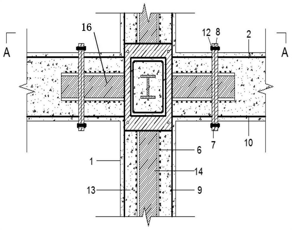
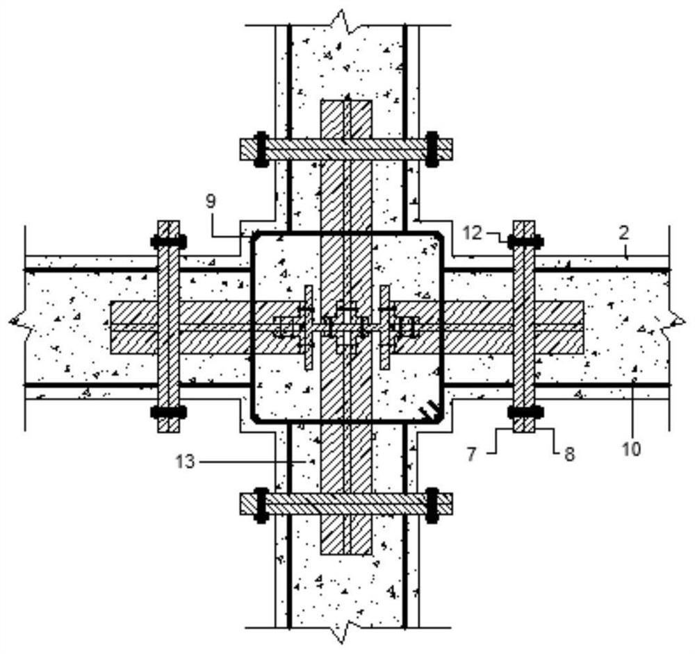
[0097] Such as Figure 1 to Figure 9 As shown, a connection node between a prefabricated steel concrete column and a reinforced concrete beam includes a prefabricated steel concrete column 1 and 1-4 prefabricated reinforced concrete beams 2 arranged along the circumference of the prefabricated steel concrete column 1;
[0098] The pouring prefabricated steel concrete column 1 is provided with longitudinal section steel 14 and 1-4 transverse section steel 16 arranged along the circumference of the longitudinal section steel 14, one end of the pouring transverse section steel 16 is connected with the longitudinal section steel 14, and the other end of the pouring transverse section steel 16 is fixedly connected There is a connecting piece 7; the pouring prefabricated steel concrete column 1 is also provided with column inner longitudinal reinforcement 9;
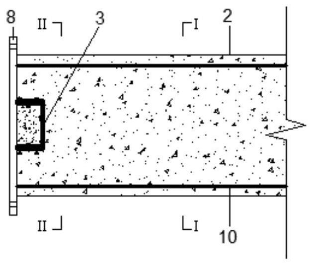
[0099] The end of the pouring prefabricated reinforced concrete beam 2 close to the prefabricated steel concrete column 1 is...
Embodiment 2
[0109] Such as Figure 10 to Figure 17 As shown, a connection node between a prefabricated steel concrete column and a reinforced concrete beam includes a prefabricated steel concrete column 1 and 1-4 prefabricated reinforced concrete beams 2 arranged along the circumference of the prefabricated steel concrete column 1;
[0110] The pouring prefabricated steel concrete column 1 is provided with longitudinal section steel 14 and 1-4 transverse section steel 16 arranged along the circumference of the longitudinal section steel 14, one end of the pouring transverse section steel 16 is connected with the longitudinal section steel 14, and the other end of the pouring transverse section steel 16 is fixedly connected There is a connecting piece 7; the pouring prefabricated steel concrete column 1 is also provided with column inner longitudinal reinforcement 9;
[0111] The end of the pouring prefabricated reinforced concrete beam 2 close to the prefabricated steel concrete column 1 ...
Embodiment 3
[0121] Such as Figure 18 to Figure 23 As shown, a connection node between a prefabricated steel concrete column and a reinforced concrete beam includes a prefabricated steel concrete column 1 and 1-4 prefabricated reinforced concrete beams 2 arranged along the circumference of the prefabricated steel concrete column 1;
[0122] The pouring prefabricated steel concrete column 1 is provided with longitudinal section steel 14 and 1-4 transverse section steel 16 arranged along the circumference of the longitudinal section steel 14, one end of the pouring transverse section steel 16 is connected with the longitudinal section steel 14, and the other end of the pouring transverse section steel 16 is fixedly connected There is a connecting piece 7; the poured prefabricated steel concrete column 1 is also provided with column inner longitudinal reinforcement 9;
[0123] The end of the pouring prefabricated reinforced concrete beam 2 close to the prefabricated steel concrete column 1 i...
PUM
 Abstract
Description
Claims
Application Information