Method of magnetically processing an iron-carbon alloy

a technology of iron-carbon alloys and magnetic processing, which is applied in the field of processing of iron-carbon alloys, can solve the problems of excessive time taken for bainite transformation, and achieve the effects of improving ductility and strength, improving mechanical properties, and high field strength

Inactive Publication Date: 2013-01-17
UT BATTELLE LLC
View PDF2 Cites 4 Cited by
  • Summary
  • Abstract
  • Description
  • Claims
  • Application Information

AI Technical Summary

Benefits of technology

[0005]Described herein is a magnetic field assisted processing method that may be used to achieve more homogeneous microstructures and improved mechanical properties in ferrous alloys. Using the method, it is possible to produce iron-carbon alloys that include a fine dispersion of iron carbide particles and exhibit a desirable combination of strength and ductility.
[0006]The method entails heating an iron-carbon alloy at an austenitizing temperature for a time duration sufficient for the alloy to achieve an austenitic microstructure; cooling the iron-carbon alloy to an intermediate temperature defined by a continuous cooling transformation (CCT) diagram for the iron-carbon alloy at a rate sufficient to avoid phase transformation of the austenitic microstructure, the intermediate temperature being below a bainitic knee of the CCT diagram and above a martensite start temperature; and applying a high field strength magnetic field of at least about 0.2 Tesla to the iron-carbon alloy after reaching the intermediate temperature. The field is applied for a time duration sufficient to transform the austenitic microstructure into a fine dispersion of one or more iron carbide phases in a ferrite matrix in order to produce a magnetically-processed alloy having improved ductility and strength.

Problems solved by technology

A downside of austempering, however, is that the transformation from austenite to bainite may take an excessively long time to occur.

Method used


Image

  • Method of magnetically processing an iron-carbon alloy
  • Method of magnetically processing an iron-carbon alloy
  • Method of magnetically processing an iron-carbon alloy

Examples


example 1

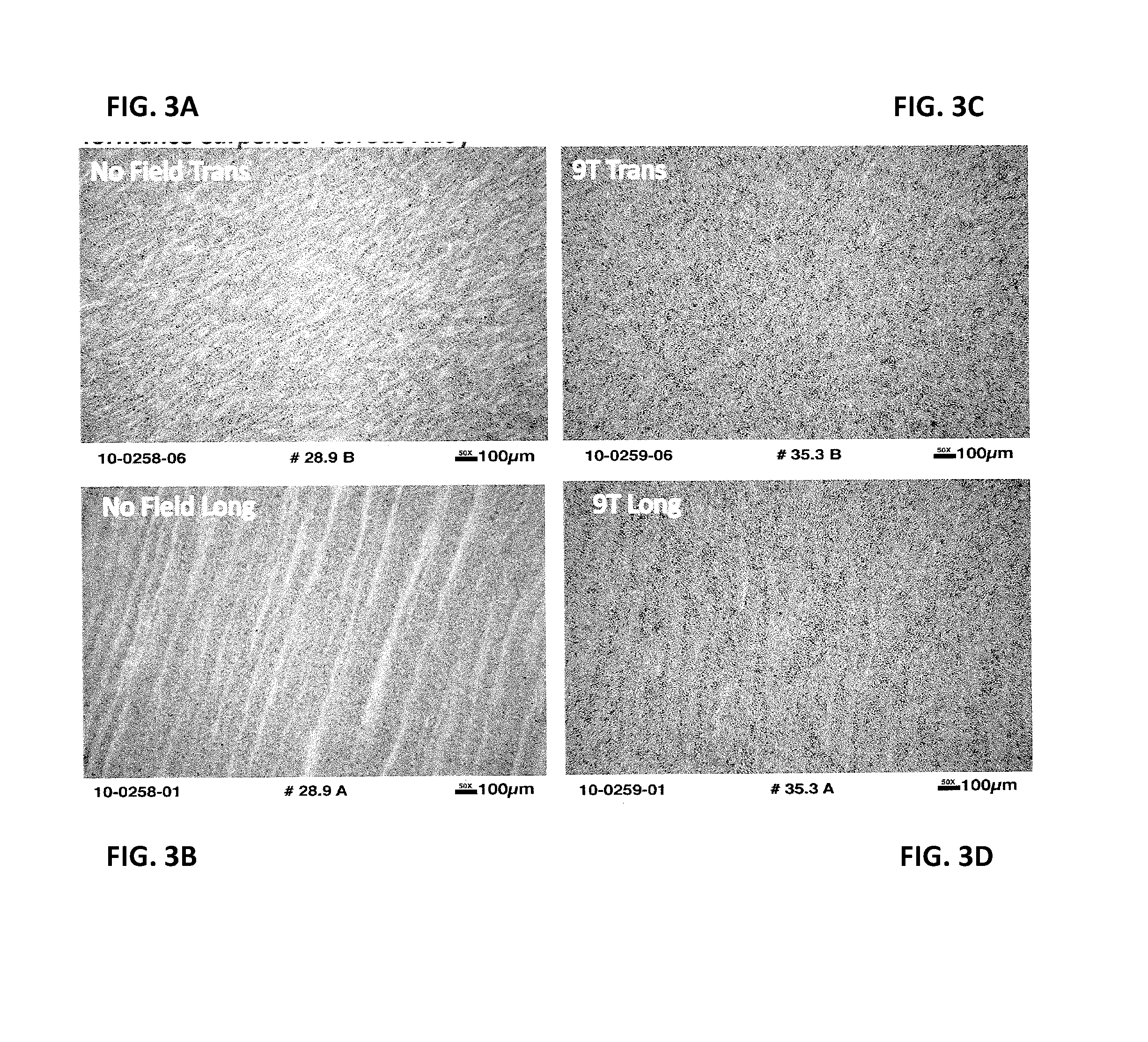
[0026]The magnetic processing method described above has been applied to low carbon, low alloy steel specimens prepared by Carpenter Technology Corporation (Wyomissing, Pa.). The chemistry of the tested alloy, where the balance is iron, is shown in Table 2.

TABLE 2Experimental Alloy CompositionElementCMnSiPSCrNiCuVTiAlN [ppm]O [ppm]wt. %0.360.780.941.263.810.520.30.004

[0027]In a series of experiments carried out using this alloy, the following experimental conditions were employed to compare the microstructure and properties when a high magnetic field was applied during the austempering process versus a reference no-field condition.

[0028]For the thermomagnetic processing runs, specimens were processed as follows prior to carrying out tensile and Charpy impact tests:[0029]Austenitized at 885° C. under a 9T field for 30 min;[0030]Helium-gas-quenched at 90 psi to 250° C.;[0031]Held at 250° C. for 8 hrs under a 9T magnetic field; and[0032]Helium-gas-quenched to room temperature.

[0033]For...


PUM

PropertyMeasurementUnit
temperatureaaaaaaaaaa
field strength magnetic fieldaaaaaaaaaa

Abstract

A magnetic field assisted processing method entails heating an iron-carbon alloy at an austenitizing temperature for a time duration sufficient for the alloy to achieve an austenitic microstructure; cooling the iron-carbon alloy to an intermediate temperature defined by a continuous cooling transformation (CCT) diagram for the iron-carbon alloy at a rate sufficient to avoid phase transformation of the austenitic microstructure, the intermediate temperature being below a bainitic knee of the CCT diagram and above a martensite start temperature; and applying a high field strength magnetic field of at least about 0.2 Tesla to the iron-carbon alloy after reaching the intermediate temperature. The field is applied for a time duration sufficient to transform the austenitic microstructure into a fine dispersion of one or more iron carbide phases in a ferrite matrix in order to produce a magnetically-processed alloy having improved ductility and strength.

Description

FEDERALLY SPONSORED RESEARCH OR DEVELOPMENT[0001]The invention described in this disclosure was made with government support under Prime Contract Number DE-AC05-000R22725 awarded by the Department of Energy. The government has certain rights in this invention.TECHNICAL FIELD[0002]The present disclosure relates generally to the processing of iron-carbon alloys and more specifically to a magnetic field-assisted processing method.BACKGROUND[0003]The thermal processing of ferrous alloys to achieve good mechanical properties has been widely studied. Most iron-carbon alloys require a rapid quench to reach a metastable martensite phase that can be transformed by heat treatment (tempered) into a desirable microstructure that exhibits good strength and toughness. During the quench, which may occur at a rate of hundreds of degrees per second, the high temperature austenitic phase rapidly cools and is transformed to martensite. Due to the volume expansion (over 4%) that occurs during the phase...

Claims


Application Information

Patent Timeline
Patent Type & Authority Applications(United States)
IPC IPC(8): C21D1/34C21D1/00C21D6/00
CPCC21D1/34C21D1/04C21D2211/005C21D1/22C21D2211/003C21D1/19
Inventor LUDTKA, GERARD M.LUDTKA, GAIL M.WILGEN, JOHN B.KISNER, ROGER A.
Owner UT BATTELLE LLC
Why Eureka
Try Eureka