Automatic stamping equipment for chain safety production

A technology for safe production and stamping equipment, applied in metal processing equipment, perforating tools, manufacturing tools, etc., can solve the problems of inability to automatically feed materials, low punching efficiency, etc., to reduce time, improve work efficiency, and prolong service life. Effect

Pending Publication Date: 2021-02-26
谢胜
View PDF10 Cites 4 Cited by
  • Summary
  • Abstract
  • Description
  • Claims
  • Application Information

AI Technical Summary

Problems solved by technology

[0006] In order to overcome the shortcomings of low steel plate punching efficiency and incapable of automatic feeding, the technical problem is to provide an automatic stamping equipment with high steel plate punching efficiency and automatic feeding chain for safe production

Method used


Image

  • Automatic stamping equipment for chain safety production
  • Automatic stamping equipment for chain safety production
  • Automatic stamping equipment for chain safety production

Examples


Embodiment 1

[0075] An automatic stamping equipment for chain safety production, such as figure 1 , figure 2 , image 3 , Figure 4 and Figure 7 As shown, it includes an underframe 1, a working plate 2, a punching mechanism 3 and a feeding mechanism 4. The top of the underframe 1 is provided with a working plate 2, the middle part of the working plate 2 is provided with a punching mechanism 3, and the right part of the working plate 2 is provided with a punching mechanism 3. There is a feeding mechanism 4.

[0076] When people are making chains, they cannot quickly punch steel plates. The present invention helps people complete the production of chains at a faster speed. In the hole mechanism 3, start the punch mechanism 3, and the punch mechanism 3 punches the steel plate. During the process, the left part of the steel plate is pulled and pulled to the left to make the discharge mechanism 4 discharge until all the steel coils are punched. Just close the punching mechanism 3, and re...

Embodiment 2

[0078] On the basis of Example 1, such as figure 2 , image 3 , Figure 4 , Figure 6 and Figure 9 As shown, the punching mechanism 3 includes a positioning frame 31, a motor 32, a special-shaped cam 33, a connecting frame 34, a pressure hole plate 35, a first return spring 36 and a worktable 37, and the middle part of the upper side of the working plate 2 is provided with a positioning frame 31 A motor 32 is installed in the middle part of the lower side of the working plate 2, and the output shafts on the front and rear sides of the motor 32 are provided with a special-shaped cam 33, and the top of the positioning frame 31 is slidably provided with a connecting frame 34, and the connecting frame 34 cooperates with the special-shaped cam 33 to connect The top of the frame 34 is provided with a pressure orifice plate 35, the upper part of the connection frame 34 is wound with four first return springs 36, the first return springs 36 are connected with the positioning fram...

Embodiment 3

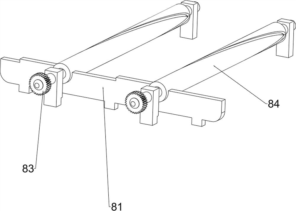
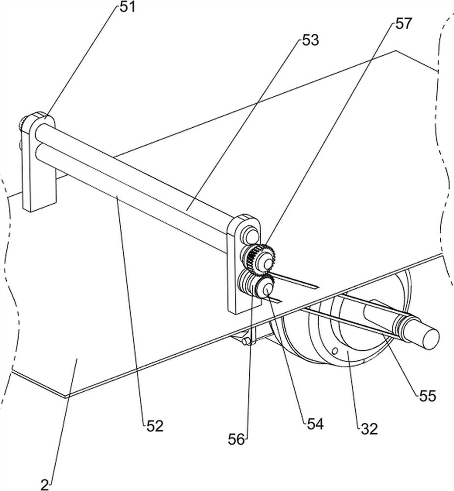
[0083] On the basis of Example 2, such as figure 1 , Figure 4 , Figure 5 , Figure 6 , Figure 7 , Figure 8 , Figure 9 and Figure 10 As shown, a main pulling mechanism 5 is also included. The middle part of the working plate 2 is provided with a main pulling mechanism 5. The main pulling mechanism 5 is connected with the punching mechanism 3. The main pulling mechanism 5 includes a second column 51, a first roller 52, The first master gear 521, the second roller 53, the first slave gear 531, the transmission shaft 54, the first pulley assembly 55, the half gear 56 and the first full gear 57, and two second columns 51 are arranged in the middle of the working plate 2 , the inner side of the middle part of the second column 51 is provided with the first roller 52, the front part of the first roller 52 is provided with the first main gear 521, and the inner side of the second column 51 is provided with the second roller 53, the second The front part of the roller 53 i...


PUM


Abstract

The invention relates to automatic stamping equipment, in particular to automatic stamping equipment for chain safety production. The automatic punching equipment for chain safety production is high in steel plate punching efficiency and capable of achieving automatic feeding; The automatic stamping equipment for chain safety production comprises a bottom frame, a working plate, a punching mechanism and a discharging mechanism, wherein the working plate is arranged on the bottom frame; the punching mechanism is arranged on the working plate; and the discharging mechanism is arranged on the working plate. According to the automatic punching equipment, the effect of quickly punching a steel plate is achieved, the pressed and punched steel plate is punched through cooperation of the punchingmechanism and a pressing mechanism, a roll of steel plate is quickly punched, the manual punching time is shortened, and the working efficiency is improved; and meanwhile, automatic feeding of the steel plate is completed through cooperation of the discharging mechanism, a main pulling mechanism and an auxiliary pulling mechanism, the steel plate is output from the discharging mechanism, and leftward movement of the steel plate is achieved through cooperation of the main pulling mechanism and the auxiliary pulling mechanism.

Description

technical field [0001] The invention relates to an automatic stamping equipment, in particular to an automatic stamping equipment for chain safety production. Background technique [0002] When people make chains, they first need to punch holes in the steel plates, and then process them to complete the chains. [0003] The material of the steel plate is relatively hard, and it is laborious to drill holes manually, and the steel plate may shift during the drilling process, resulting in a messy arrangement of holes and sharp edges of the steel plate, which may cut hands when replacing the steel plate. [0004] The publication number is CN211515716U, which discloses an automatic stamping equipment for aluminum coils, which belongs to the technical field of aluminum coils. The automatic stamping equipment for aluminum coils includes a frame, a stamping mechanism, a moving mechanism and a limit mechanism. a box body and an upper frame body, the upper frame body is fixed on the t...

Claims


Application Information

Patent Timeline
Patent Type & Authority Applications(China)
IPC IPC(8): B21D28/26B21D28/34B21D43/09
CPCB21D28/26B21D28/34B21D43/09
Inventor 谢胜
Owner 谢胜
Why Eureka
Try Eureka