Auxiliary drilling device for integrated circuit board

A technology for integrated circuit boards and drilling devices, which is applied to printed circuits, printed circuit manufacturing, electrical components, etc. It can solve the problems of inconvenient waste, turning holes, and unable to collect circuit boards, etc., and achieve the effect of maintaining stability and facilitating collection

Active Publication Date: 2021-03-12
固安恩喜友电路板有限公司
View PDF10 Cites 2 Cited by
  • Summary
  • Abstract
  • Description
  • Claims
  • Application Information

AI Technical Summary

Problems solved by technology

[0004] In order to overcome the disadvantages of the prior art that require many steps of manual operation, that it is inconvenient for people to collect the waste generated when the holes are turned, and that it is impossible to better turn the holes at different positions of the circuit board, the technical problem of the present invention is: to provide An integrated circuit board auxiliary drilling device that can adjust the position of the hole, has a high degree of automation, and is convenient for people to collect the waste generated when the hole is turned

Method used


Image

  • Auxiliary drilling device for integrated circuit board
  • Auxiliary drilling device for integrated circuit board
  • Auxiliary drilling device for integrated circuit board

Examples


Embodiment 1

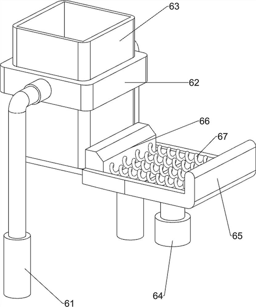
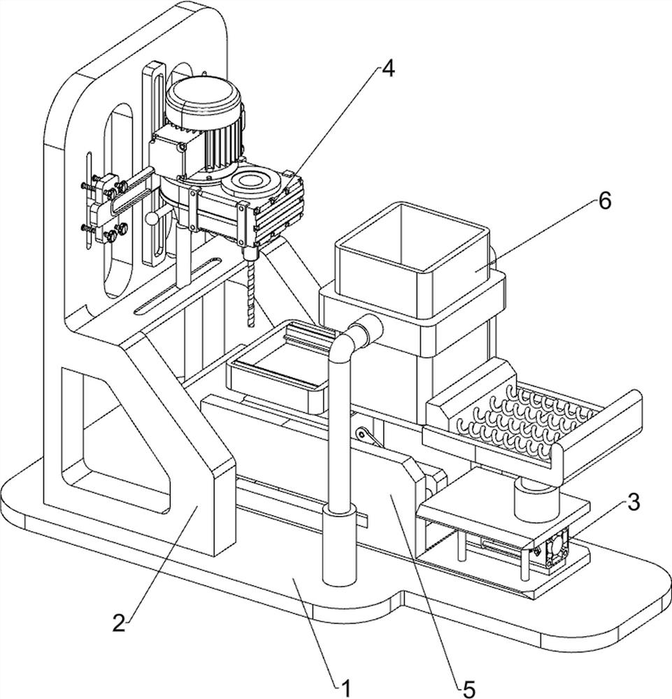
[0026] An integrated circuit board auxiliary drilling device, such as figure 1 , figure 2 , image 3 and Figure 4 As shown, it includes a bottom plate 1, a workbench 2, a lifting mechanism 3, a punching mechanism 4 and a reciprocating feeding mechanism 5. A workbench 2 is provided on the left side of the top of the bottom plate 1, and a lifting mechanism 3 is provided on the bottom plate 1 and the workbench 2. , The lifting mechanism 3 is provided with a punching mechanism 4, and the bottom plate 1 is provided with a reciprocating feeding mechanism 5.

[0027] When people need to use this device, first people place the circuit board on the reciprocating feeding mechanism 5, and fix the circuit board, then people can start the punching mechanism 4 and the lifting mechanism 3, and the lifting mechanism 3 drives the reciprocating feeding mechanism 5 Operation, the reciprocating feeding mechanism 5 operates and then drives the circuit board to move upwards. When the circuit b...

Embodiment 2

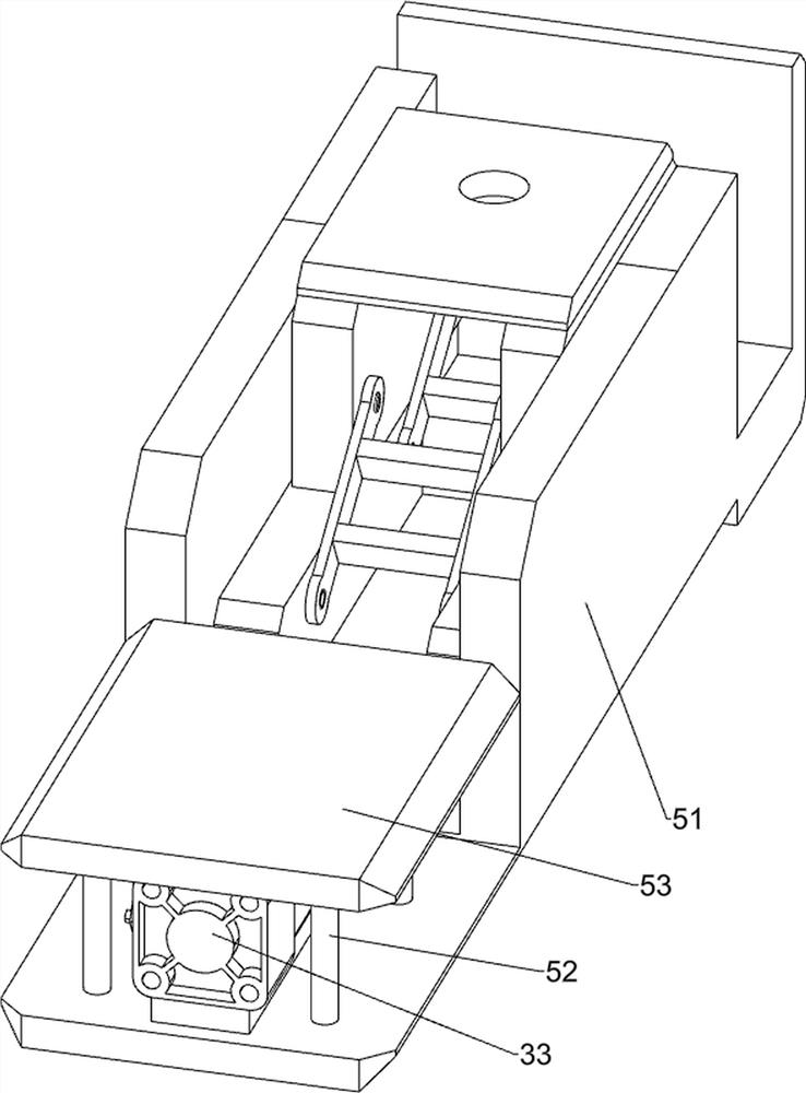
[0029] On the basis of Example 1, such as figure 1 , Figure 5 , Figure 6 and Figure 7 As shown, the lifting mechanism 3 includes a lifting rod 31, a first guide sleeve 32 and a cylinder 33, the first guide sleeve 32 is slidably provided on the workbench 2, the lifting rod 31 is slidably provided on the first guide sleeve 32, and the bottom plate 1 top right side is provided with cylinder 33.

[0030] The punching mechanism 4 includes a servo motor 41, a gearbox 42, a second guide sleeve 43, a threaded punch 44, a support rod 45 and a first fixed plate 46. The elevating rod 31 is provided with a gearbox 42, and the gearbox 42 is installed There is a servo motor 41, a second guide sleeve 43 is provided on the output shaft of the transmission case 42, a threaded punch 44 is provided on the second guide sleeve 43, a support rod 45 is symmetrically provided on the transmission case 42, and a second guide sleeve 43 is provided on the transmission case 42. A fixed plate 46.

...


PUM


Abstract

The invention relates to a drilling device, in particular to an auxiliary drilling device for an integrated circuit board. According to the auxiliary drilling device for the integrated circuit board,the hole drilling position can be adjusted, the automation degree is higher, and people can conveniently collect waste generated in the hole drilling process. The auxiliary drilling device for the integrated circuit board comprises a bottom plate, lifting mechanisms, punching mechanisms and a reciprocating feeding mechanism. A workbench is arranged on the bottom plate; the lifting mechanisms are arranged on the bottom plate and the workbench; the punching mechanisms are arranged on the lifting mechanisms; and the reciprocating feeding mechanism is arranged on the bottom plate. The reciprocating feeding mechanism is driven by the lifting mechanisms to operate, then rapid punching of the circuit board is achieved under cooperation of the punching mechanisms, and the reciprocating feeding mechanism can drive the circuit board to move up and down.

Description

technical field [0001] The invention relates to a drilling device, in particular to an auxiliary drilling device for an integrated circuit board. Background technique [0002] Circuit boards are mostly used in electronic technology. After the circuit board is manufactured, it usually needs to go through multiple processes. Among them, the hole-turning process is a more important one in the processing steps. The hole-turning devices in the current market usually require manual operation. There are many steps, and it needs to be manually loaded during processing, and the existing hole-turning device is usually complicated in structure, and it is not convenient for people to collect the waste generated during hole-turning. In addition, circuit boards of different sizes need to be processed. The holes are rotated at different positions, and the existing punching devices are usually fixed, which is inconvenient. [0003] Therefore, there is an urgent need to develop an integrate...

Claims


Application Information

Patent Timeline
Patent Type & Authority Applications(China)
IPC IPC(8): B26F1/16B26D7/26B26D7/32B26D7/06H05K3/00
CPCB26F1/16B26D7/2614B26D7/2628B26D7/32B26D7/0616H05K3/0047B26F2210/08B26D2007/322Y02W30/82
Inventor 颜斌
Owner 固安恩喜友电路板有限公司
Why Eureka
Try Eureka