Special fixture for tenon root machining for blade of aviation engine

A special fixture and blade technology, applied in the direction of manufacturing tools, metal processing equipment, metal processing machinery parts, etc., can solve problems such as wear and increase processing errors, and achieve accurate positioning, fast positioning and clamping, and simple structure.

Inactive Publication Date: 2018-01-09
NORTHWESTERN POLYTECHNICAL UNIV
View PDF5 Cites 20 Cited by
  • Summary
  • Abstract
  • Description
  • Claims
  • Application Information

AI Technical Summary

Problems solved by technology

However, the clamp body needs to be taken out from the base and turned over 180° before being loaded into the base during processing. Multiple clamping processes will cause wear on the interference contact surface between the clamp body and the base, thereby increasing the processing error

Method used


Image

  • Special fixture for tenon root machining for blade of aviation engine
  • Special fixture for tenon root machining for blade of aviation engine
  • Special fixture for tenon root machining for blade of aviation engine

Examples


Embodiment Construction

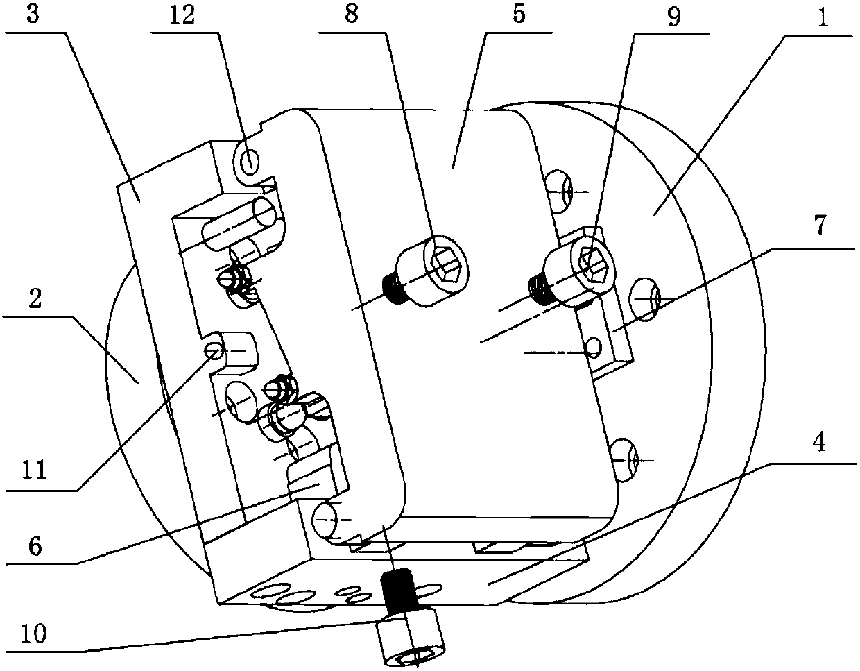
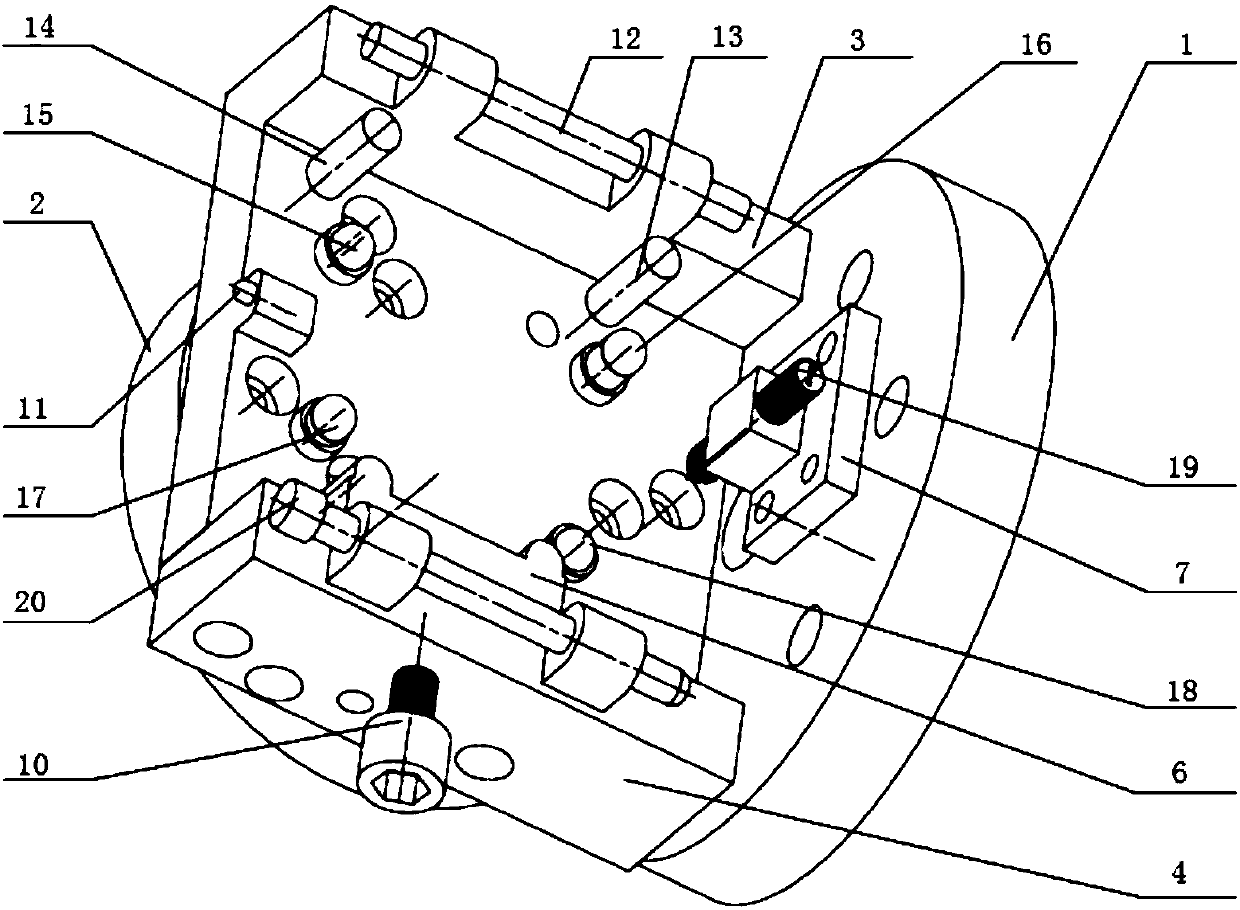
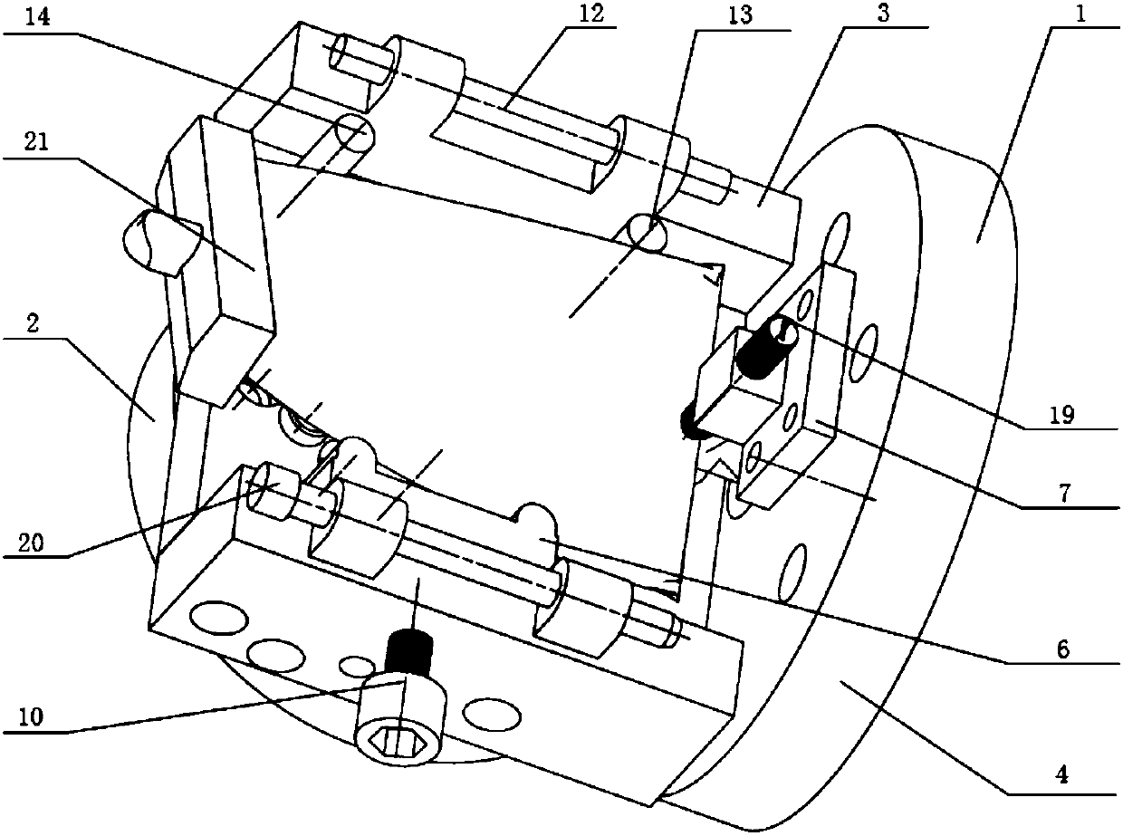
[0022] This embodiment is a special fixture used for processing the mortise root of an aeroengine blade.

[0023] refer to Figure 1 ~ Figure 4 , the present embodiment is used for the special fixture of aero-engine blade mortise root processing, consists of the first rotary table 1, the second rotary table 2, the rear plate of the base 3, the front plate of the base 4, the upper cover 5, the floating slider 6, Clamping bump 7, first clamping nut 8, second clamping nut 9, third clamping nut 10, shoulder positioning pin 11, first pin shaft 12, first positioning pin 13, second positioning pin 14 , the first ball stud alignment pin 15, the second ball stud alignment pin 16, the third ball stud alignment pin 17, the fourth ball stud alignment pin 18, the clamping screw 19, the second bearing pin 20, and the pin 22; wherein , the first rotary table 1 is connected to the main shaft of the machine tool, the first rotary table 1, the second rotary table 2 are fixedly connected with t...


PUM


Abstract

The invention discloses a special fixture for tenon root machining for the blade of an aviation engine. According to the fixture, one-time clamping and six-point location are adopted, vibration attenuation is carried out on the contact part of each location pin head and the blade through a resin material, and vibration can be effectively suppressed in a machining process, so that the deformation of the tenon root part of the blade during machining is reduced, and damage is avoided; and the fixture realizes location and clamping for the blade through the buckling of an upper cover and a base. Arotary workbench is connected with a machine tool, a main shaft rotates to drive the rotary workbench and the fixture to rotate, and continuous machining for the whole tenon root is completed throughone-time clamping; and a clamping nut drives a floating slide block to clamp under a clamping force, and adequate contact and the balanced clamping force are ensured while clamping is ensured. The fixture carries out rapid location and clamping for the blade body part of the blade in a blade clamping process, is simple in structure, high in location accuracy, and convenient and fast in blade installation-detachment operation, and effectively saves time and cost on the premise of ensuring the machining quality, thereby realizing efficient batch production for blades.

Description

technical field [0001] The invention relates to the technical field of precise and ultra-precise numerical control machining of aeroengine blades, in particular to a special fixture used for machining aeroengine blade mortise roots. Background technique [0002] The blade is a key component of an aero-engine, and its manufacturing quality seriously affects the overall quality of the entire aero-engine. As the requirements for aero-engines become more and more stringent, the design precision of blades continues to increase. At present, the blade has the following characteristics: the blade is a thin-walled part, and the curved surface of the blade body is a complex free-form surface with severe bending and torsion to improve aerodynamic performance; the material of the blade is a titanium alloy material to reduce the mass and improve the strength. In the traditional processing of blades, precision forging is first carried out so that the blade body can be formed at one time ...

Claims


Application Information

Patent Timeline
Patent Type & Authority Applications(China)
IPC IPC(8): B23Q3/06
Inventor 蔺小军吴刚肖群宝崔清清杨懿晨田楚伦李雅琦
Owner NORTHWESTERN POLYTECHNICAL UNIV
Why Eureka
Try Eureka