Shielding sleeve and connector with same

A technology for shielding sleeves and connectors, which is applied in the directions of connection, parts of connection devices, fixed/insulated contact members, etc., can solve the problems of difficult assembly, complex structure, high manufacturing and use costs, and achieve convenient assembly and simple structure. Effect

Active Publication Date: 2017-05-31
CHINA AVIATION OPTICAL-ELECTRICAL TECH CO LTD
View PDF8 Cites 19 Cited by
  • Summary
  • Abstract
  • Description
  • Claims
  • Application Information

AI Technical Summary

Problems solved by technology

However, most of the existing plug connectors with shielding function have

Method used


Image

  • Shielding sleeve and connector with same
  • Shielding sleeve and connector with same
  • Shielding sleeve and connector with same

Examples


Embodiment Construction

[0026] Embodiments of the present invention will be further described below in conjunction with the accompanying drawings.

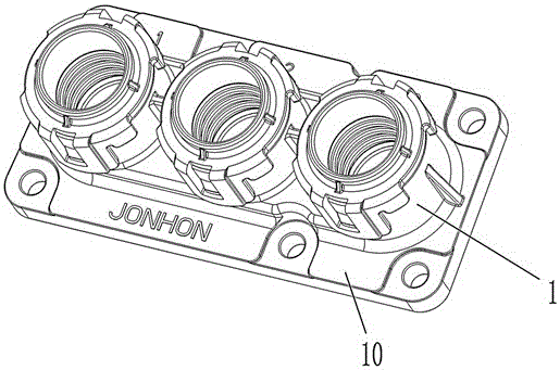
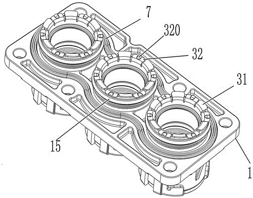
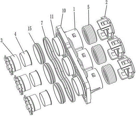
[0027] Specific embodiments of the connector of the present invention, such as Figure 1 to Figure 5 As shown, it includes a connector housing 1, and the outer side of the connector housing 1 is provided with a connecting flange 10. When in use, it is installed on the installation panel of the equipment through the connecting flange 10, and the installation panel is provided with a connector wire The stepped hole through which the cable passes, the large-diameter end of the stepped hole is located on the outside of the installation panel. The connector housing 1 is provided with three threading holes perpendicular to the installation panel. Of course, in other embodiments, the number of threading holes can be one, two or more than four, which can be set according to the use environment, and no specific limitation is set here. A shielding sleeve 3 is in...


PUM


Abstract

The invention provides a shielding sleeve and a connector with the same. More than one threading hole perpendicular to a mounting face plate is formed in a connector shell, and the shielding sleeve applicable to being in contact with shielding layers of cables is mounted in the corresponding threading hole. The front end of the shielding sleeve extends out of the front end of the corresponding threading hole. The shielding sleeve comprises a sleeve. Elastic arms which are elastically compressed with stepped surfaces of a stepped hole in the mounting face plate in a jacking manner during use are outwardly folded at the front end of the sleeve, and folding angles of the elastic arms are smaller than 90 degrees. The shielding sleeve and the connector have the advantages that the shielding layers, which penetrate the corresponding threading hole, of the cables are in contact with the shielding sleeve made of metal materials when the connector is used, then the shielding sleeve is in elastic contact with the stepped surfaces of the stepped hole in the mounting face plate via the elastic arms at the front end of the shielding sleeve, and accordingly shielding effects can be realized; the connector is simple in structure and convenient to assemble.

Description

technical field [0001] The invention relates to conductive connection equipment, in particular to a shielding sleeve and a connector using the shielding sleeve. Background technique [0002] When connecting cables to the inside of the equipment box, a connector is often installed on the panel of the box, that is, a plug connector, through which the cable passing through the cable hole on the panel is fixed and sealed . In some usage environments, the plug connector is also required to shield the electric field generated by the cable. However, most of the existing plug connectors with shielding function have complex structures, difficult assembly, and high manufacturing and use costs. Contents of the invention [0003] The object of the present invention is to provide a plug connector with simple structure and shielding function; at the same time, the present invention also provides a shielding sleeve suitable for the plug connector. [0004] The shielding sleeve of the ...

Claims


Application Information

Patent Timeline
IPC IPC(8): H01R13/40H01R13/502H01R13/6581
Inventor 娄鹏郭辉宋泳斌张星
Owner CHINA AVIATION OPTICAL-ELECTRICAL TECH CO LTD
Why Eureka
Try Eureka