Pipeline cutting machine

A technology of pipe cutting machine and slideway, which is applied to pipe shearing devices, shearing devices, metal processing machinery parts, etc., can solve the problems of low safety and inaccurate cutting, and achieve high safety, good collection, and cost of construction. low effect

Inactive Publication Date: 2020-06-09
仪征市金银无纺包装材料有限公司
View PDF6 Cites 17 Cited by
  • Summary
  • Abstract
  • Description
  • Claims
  • Application Information

AI Technical Summary

Problems solved by technology

[0005] In order to overcome the shortcomings of manual hand-held operations in many processing sites at present, there is separation between the jig and the cutting knife in hand-held cutting, and poo

Method used


Image

  • Pipeline cutting machine
  • Pipeline cutting machine
  • Pipeline cutting machine

Examples


Embodiment 1

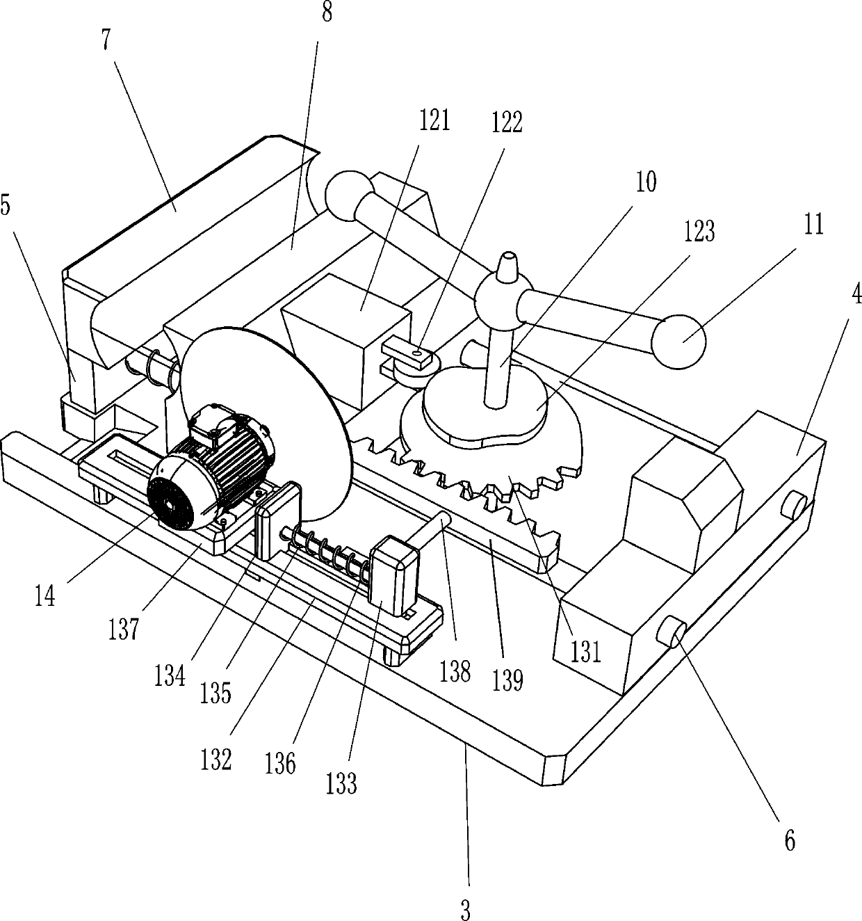
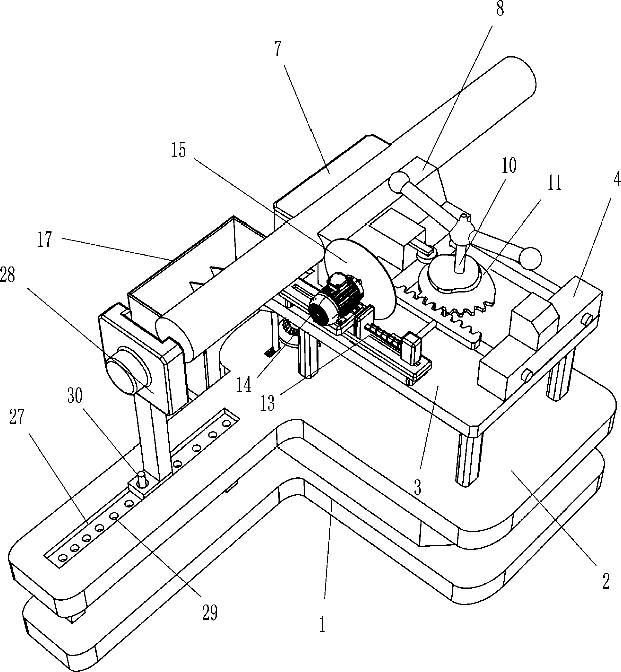
[0022] Such as Figure 1-3 As shown, a pipe cutting machine includes a base 1, a support plate 2, a workbench 3, a first fixed block 4, a second fixed block 5, a guide rod 6, a fixed clamp block 7, a movable clamp block 8, a first Elastic part 9, rotating rod 10, handle 11, extruding mechanism 12, moving device 13, rotating motor 14, circular cutter 15, slideway 16 and collection frame 17, base 1 top is provided with support plate 2, support plate 2 The top is provided with a workbench 3, and the second fixed block 5 and the first fixed block 4 are symmetrically arranged on the left and right sides of the top of the workbench 3, and a guide rod 6 is arranged front and back symmetrically between the first fixed block 4 and the second fixed block 5, The top of the second fixed block 5 is provided with a fixed clip 7, and the two guide rods 6 are slidably provided with a movable clip 8, and a first elastic member 9 is arranged symmetrically between the movable clip 8 and the fixe...

Embodiment 2

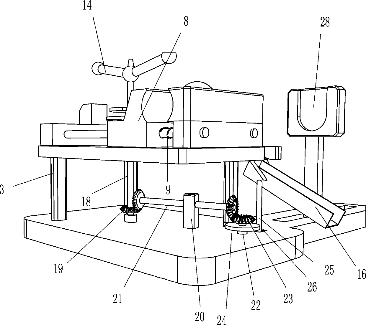
[0027] On the basis of Example 1, such as figure 1 and 3Shown, also include rotating rod 18, first bevel gear 19, bearing block 20, rotating shaft 21, rotating shaft 22, second bevel gear 23, beat wheel 24, ejector rod 25 and the 3rd elastic member 26, rotating rod The lower end of the 10 is connected with a rotating rod 18 through a coupling, the rotating rod 18 is provided with a first bevel gear 19, the top of the base 1 is provided with a bearing seat 20, the bearing seat 20 is provided with a rotating shaft 21, and the right end of the rotating shaft 21 is provided with a first cone Gear 19, two first bevel gears 19 are meshed with each other, base 1 is provided with rotating shaft 22 in the left side rotation type, the left end of rotating shaft 21 and the middle part of rotating shaft 22 are all provided with second bevel gear 23, and two second bevel gears 23 are meshed with each other, The lower part of the rotating shaft 22 is provided with a beating wheel 24 throug...


PUM


Abstract

The invention relates to a cutting machine, in particular to a pipeline cutting machine. The pipeline cutting machine is high in safety and low in manufacturing cost and integrates clamping and cutting. The pipeline cutting machine comprises a base, a supporting plate, a workbench, a first fixing block, a second fixing block, guide rods, a fixed clamping block, a movable clamping block, a first elastic piece, a rotating rod, a handle and the like; and the supporting plate is arranged at the top of the base, the workbench is arranged at the top of the supporting plate, the first fixing block and the second fixing block are symmetrically arranged on two sides of the top of the workbench, the guide rods are symmetrically arranged between the first fixing block and the second fixing block, andthe fixed clamping block is arranged at the top of the second fixing block. The pipeline cutting machine achieves the effects of high safety, low manufacturing cost and integration of clamping and cutting.

Description

technical field [0001] The invention relates to a cutting machine, in particular to a pipe cutting machine. Background technique [0002] In all kinds of machinery manufacturing. In the process of pipeline installation, it is always necessary to cut and blank some pipelines such as stainless steel, alloy steel and carbon steel. Although there are magnetic semi-automatic cutting equipment at present, due to the complexity of the equipment, the high price, and the limited material of the workpiece that can be cut, there are still many disadvantages in using it, especially in construction processing, mechanical processing, and small batch parts processing. Magnetic semi-automatic cutting equipment is not tried. . [0003] At present, many processing sites are manually operated with hand-held operations. Hand-held cutting has the disadvantages of separation of fixtures and cutting knives, and poor coordination is prone to inaccurate cutting and low safety. [0004] Therefore,...

Claims


Application Information

Patent Timeline
IPC IPC(8): B23D21/00B23D33/02B23D33/00B23Q3/06B23Q11/00
CPCB23D21/00B23D33/00B23D33/02B23Q3/06B23Q11/0042
Inventor 刘东连
Owner 仪征市金银无纺包装材料有限公司
Why Eureka
Try Eureka