
Waste compression device

A compression device and waste material technology, applied in the direction of presses, metal processing, manufacturing tools, etc., can solve the problems of large internal gaps, frequent replacement of collection bags, unfavorable transfer and storage, etc., and achieve the effect of facilitating collection

Pending Publication Date: 2019-04-30
WUXI LEAD INTELLIGENT EQUIP CO LTD
View PDF0 Cites 0 Cited by
  • Summary
  • Abstract
  • Description
  • Claims
  • Application Information

AI Technical Summary

Problems solved by technology

[0002] The waste produced after the laser die-cutting of the pole piece is generally collected by the blower and then bagged for unified treatment. However, since the waste collected directly by the blower has not been squeezed and other processes, the internal gap is large, and the receiving bag needs to be replaced frequently. It is also not conducive to subsequent transshipment and storage

Method used

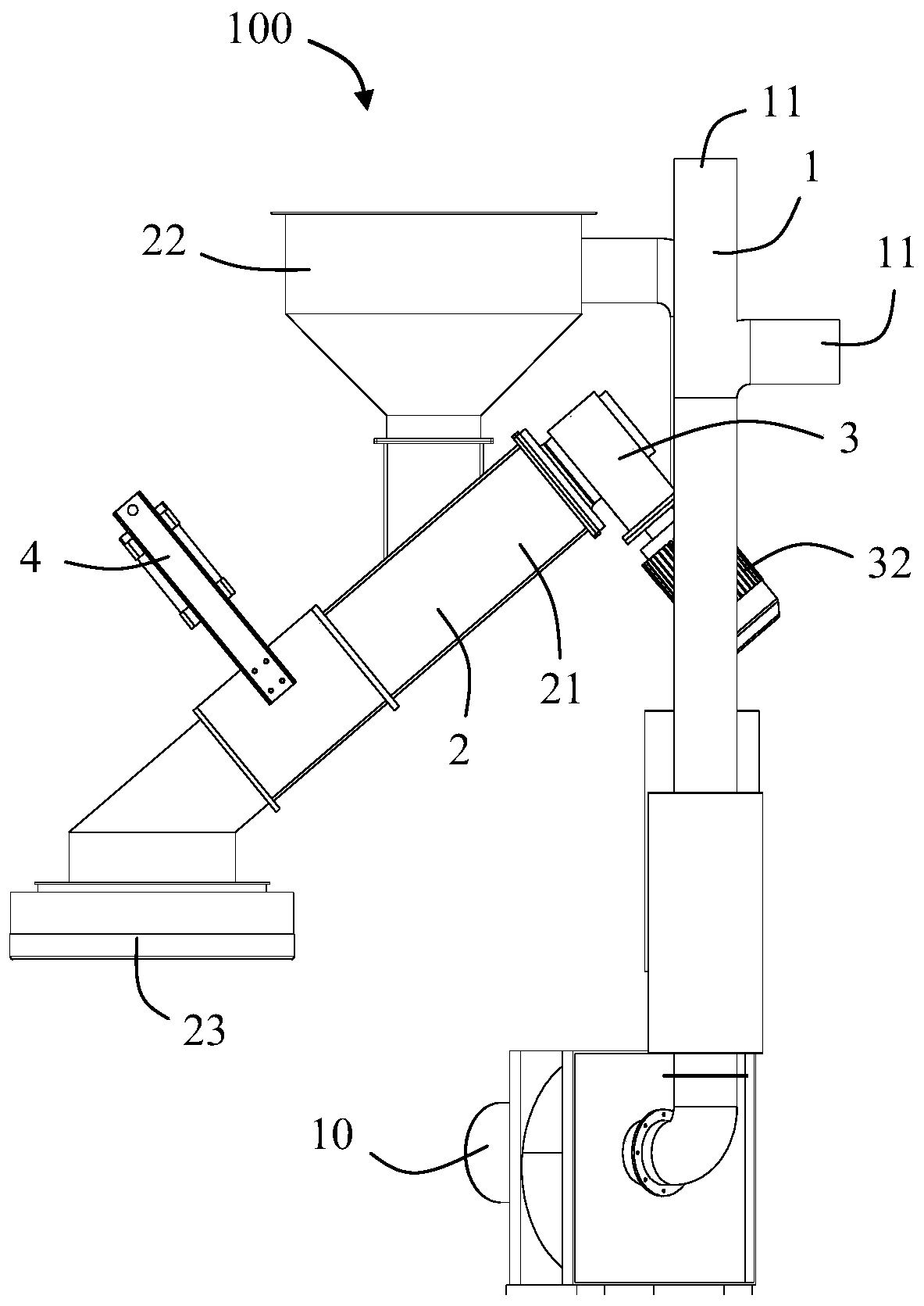
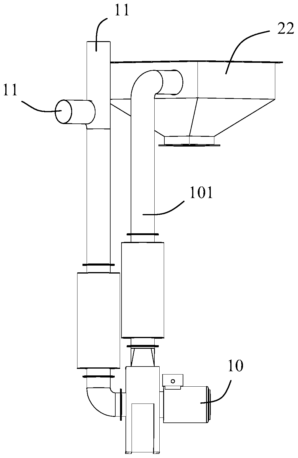
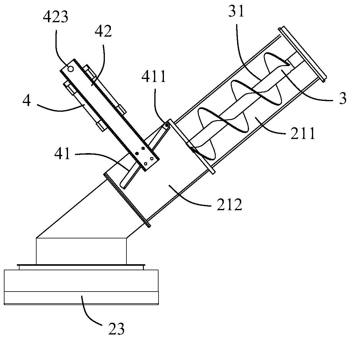

Image

  • Waste compression device
  • Waste compression device
  • Waste compression device

Examples


Embodiment Construction

[0021] Please refer to Figure 1 to Figure 5 As shown, the present invention discloses a waste material compression device 100 , which includes a waste material collection part 1 and a waste material compression part 2 , wherein the waste material collection part 1 includes a waste material collection driving device and a waste material inlet 11 . The waste collection driving device is used to provide a power source to make waste enter the waste material inlet 11 . In the illustrated embodiment of the present invention, the waste collection driving device is a blower 10, and the blower 10 is connected to the waste feed port 11 through a pipeline for sucking waste to be collected.

[0022] The waste compression part 2 includes a discharge pipeline 21 connected to the waste material inlet 11 and a first compression mechanism 3 and a second compression mechanism for compressing the waste in the discharge pipeline 21 twice. 4. In one embodiment of the present invention, the blow...


PUM


Abstract

The invention discloses a waste compression device which comprises a waste collection portion and a waste compression portion, wherein the waste collection portion comprises a waste feeding hole and awaste collection drive device used for providing a power source to enable wastes to enter the waste feeding hole; the waste compression portion comprises a discharge pipeline connected with the wastefeeding hole, a first compression mechanism and a second compression mechanism; the first compression mechanism and the second compression mechanism are used for carrying out twice compression on thewaste in the discharge pipeline. For the waste compression device, with such arrangement, the discharged wastes are relatively small in size through twice squeezing, and subsequent collection is facilitated.

Description

technical field [0001] The invention relates to a waste material compression device, which belongs to the technical field of automation equipment. Background technique [0002] The waste produced after the laser die-cutting of the pole piece is generally collected by the blower and then bagged for unified treatment. However, since the waste collected directly by the blower has not been squeezed and other processes, the internal gap is large, and the receiving bag needs to be replaced frequently. It is also not conducive to subsequent transshipment and storage. [0003] Therefore, there is an urgent need to find a waste compression device that can reduce the volume of waste. Contents of the invention [0004] The object of the present invention is to provide a waste compressing device capable of compressing waste to reduce its volume. [0005] In order to achieve the above object, the present invention adopts the following technical solution: a waste material compression ...

Claims


Application Information

Patent Timeline
IPC IPC(8): B26D7/18B30B9/00
CPCB26D7/1863B30B9/00
Inventor 不公告发明人
Owner WUXI LEAD INTELLIGENT EQUIP CO LTD
Learn More