Die base of stamping press and stamping press

A technology of a die base and a punching machine, applied in the field of punching equipment, can solve problems such as time-consuming, inconvenient replacement, affecting production, etc., and achieve the effect of improving processing efficiency and changing the die quickly and easily.

Active Publication Date: 2017-08-18
ZHEJIANG SHENGDA STEEL TOWER
View PDF8 Cites 3 Cited by
  • Summary
  • Abstract
  • Description
  • Claims
  • Application Information

AI Technical Summary

Problems solved by technology

[0003] However, only one punch and one die can be installed on the punching die of the existing punching machine. When processing sheets with the same aperture and different thicknesses, the die needs to be replaced. This replacement is inconvenient and takes a long time, which affects Production

Method used


Image

  • Die base of stamping press and stamping press
  • Die base of stamping press and stamping press
  • Die base of stamping press and stamping press

Examples


Embodiment 1

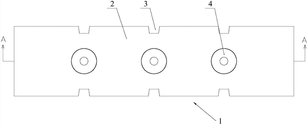
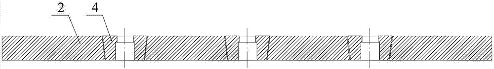
[0041] Such as figure 1 and 2 As shown, a die base 1 of a stamping machine includes a body 2. The body 2 has a plurality of die grooves, and each die groove is equipped with a die 4 of different sizes, and the axes of each die groove are located at the same on flat surface.

[0042] In this embodiment, the main body 2 is strip-shaped, and the two long side walls of the main body 2 have card slots 3; The distance is the same as the distance between two adjacent die grooves. Setting the card slot 3 can facilitate the positioning and fixing of the main body 2 after it is moved into place.

[0043] Multiple dies 4 are installed on the die base 1 at the same time. When processing the same aperture, the diameter of the cutting edge of the die 4 is determined according to the thickness range of the sheet to be processed. At this time, only the body 2 needs to be moved so that the corresponding die 4 slide to the position of the center line of the hydraulic shaft, and the punching...

Embodiment 2

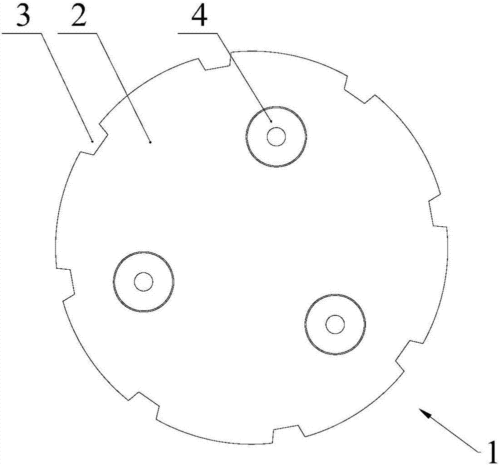
[0045] Such as image 3 As shown, a die base 1 of a stamping machine includes a body 2, and the body 2 has a plurality of die grooves, each die groove is arranged around the axis of the body 2, and the distance between the axis of each die groove and the axis of the body 2 is All are equal, and the die 4 of different size is installed on each die groove.

[0046] In this embodiment, the body 2 is cylindrical, and the die grooves are uniformly distributed around the axis of the body 2 , and a plurality of locking grooves 3 are evenly distributed on the outer wall of the body 2 along the circumferential direction.

[0047] Multiple dies 4 are installed on the base 1 of the die at the same time. When processing the same aperture, the cutting edge diameter of the die 4 is determined according to the thickness range of the sheet to be processed. At this time, only the body 2 needs to be rotated so that the corresponding die 4 slide to the position of the center line of the hydraul...

Embodiment 3

[0049] Such as Figure 4 As shown, a stamping machine includes:

[0050] Rack 11;

[0051] Die base 1, die base 1 is the die base in embodiment 1;

[0052] Push the switching mechanism, used to push the die base 1 to reciprocate relative to the frame 11;

[0053] The limit mechanism is used to limit the die base 1 after the die base 1 is moved into place.

[0054] In this embodiment, the push switch mechanism includes a switch cylinder 10 , and the piston rod of the switch cylinder 10 is fixed to the die base 1 .

[0055] In this embodiment, the body 2 is strip-shaped, and the two long side walls of the body 2 have card slots 3, and the die slots are arranged at equal intervals, and the card slots 3 are arranged at equal intervals, and the adjacent two card slots 3 The distance is the same as the distance between two adjacent die grooves;

[0056] Limiting mechanisms include:

[0057] The limit block 7 is slidably arranged on one side of the body 2, and the limit block 7...


PUM


Abstract

The invention discloses a die base of a stamping press and the stamping press. The die base comprises a body, and a plurality of die cavities are formed in the body. Dies with different sizes are mounted on the die cavities, and the axes of the die cavities are positioned on the same plane. A plurality of dies are simultaneously mounted on the die base. When the same bore diameter is processed, the point diameters of the dies are determined according to the thickness range of a processed sheet; only the body needs to move at the moment, the corresponding die can slide to the center line of a hydraulic shaft; after the body is fixed, the die can be punched. The die base is convenient and fast to replace the die and can greatly improve the processing benefit.

Description

technical field [0001] The invention relates to punching equipment, in particular to a die base of the punching machine and the punching machine. Background technique [0002] The stamping machine drives the flywheel through the motor, and through the clutch, the transmission gear drives the crank linkage mechanism to move the slider up and down, and drives the mold to form the steel plate. The patent document with the application number 201220449426.1 discloses a stamping machine, including a machine base, a vertical rod arranged on the machine base, and a working platform arranged on the machine base. A hydraulic power device is arranged in the machine base, and the hydraulic power device There is a hinge connection mechanism externally, and a flywheel mechanism is set on the top of the pole, and one end of the hinge connection mechanism is connected to the flywheel mechanism on the pole, and a stamping device is connected to the lower end of the flywheel mechanism; oil is...

Claims


Application Information

Patent Timeline
Patent Type & Authority Applications(China)
IPC IPC(8): B21D28/14B21D37/04
CPCB21D28/14B21D37/04
Inventor 蔡威斌陈卫波黄元勋周丛永林捷许俊林何路
Owner ZHEJIANG SHENGDA STEEL TOWER
Why Eureka
Try Eureka