
Method and system for creating three-dimensional virtual image of dental patient

A three-dimensional virtual and patient technology, applied in image enhancement, image analysis, medical images, etc., can solve the problems of low accuracy in dental aesthetic restoration and occlusal reconstruction, and achieve the effect of accurate and convenient occlusal reconstruction

Pending Publication Date: 2021-02-26
TONGJI UNIV
View PDF4 Cites 2 Cited by
  • Summary
  • Abstract
  • Description
  • Claims
  • Application Information

AI Technical Summary

Benefits of technology

The current methods used for making 3D images involve combining multiple scans into one composite picture that helps professionals see better detail about teeth or other parts during medical procedures. This makes it easier than just looking at them alone without actually taking their mouth offline.

Problems solved by technology

Technological Problem addressed in this patented technical problem involves creation of customized orthodontic brackets during surgeries due to factors like missing teeth caused by accidental drilling procedures or poor alignment from previous treatments. Current methods involve taking impressions before making any repairs, leading to potential complications including gingival recession, root resoφtion, and lack of esthealthy contact surfaces around posterior teeth. Additionally, current techniques require complicated workflow processes and tools to guide the process, resulting in increased costs compared to direct restoring without these featured materials.

Method used


Image

  • Method and system for creating three-dimensional virtual image of dental patient
  • Method and system for creating three-dimensional virtual image of dental patient

Examples


Embodiment 1

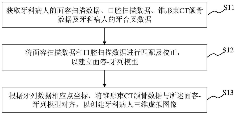
[0031] This embodiment provides a method for creating a three-dimensional virtual image of a dental patient, including:

[0032] Obtain facial scan data, oral scan data and cone-beam CT jaw data of dental patients;

[0033] matching and correcting the face scan data and the oral cavity scan data to establish a face-dentition model;

[0034] According to the corresponding point coordinates of the dentition data, the cone-beam CT jaw data is aligned with the face-dentition model to create a three-dimensional virtual image of the dental patient.

[0035] The method for creating a three-dimensional virtual image of a dental patient provided by this embodiment will be described below with reference to illustrations. see figure 1 , is shown as a schematic flowchart of a method for creating a three-dimensional virtual image of a dental patient in an embodiment. Such as figure 1 As shown, the method for creating a three-dimensional virtual image of a dental patient specifically in...

Embodiment 2

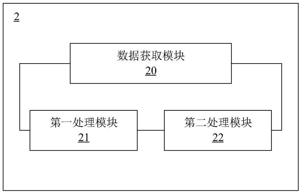
[0061] This embodiment provides a system for creating a three-dimensional virtual image of a dental patient, including:

[0062] The data acquisition module is used to acquire facial scan data, oral cavity scan data and cone-beam CT jaw bone data of dental patients;

[0063] The first processing module is used to match and correct the face scan data and the oral cavity scan data to establish a face-dentition model;

[0064] The second processing module aligns the cone-beam CT jaw data with the face-dentition model according to the corresponding point coordinates of the dentition data, so as to create a three-dimensional virtual image of the dental patient.

[0065] The system for creating a three-dimensional virtual image of a dental patient provided by this embodiment will be described in detail below with a collection of illustrations. see figure 2 , is shown as a schematic structural diagram of a system for creating a three-dimensional virtual image of a dental patient i...


PUM


Abstract

The invention provides a method and a system for creating a three-dimensional virtual image of a dental patient. The method for creating the three-dimensional virtual image of the dental patient comprises the following steps: acquiring facial scanning data, oral scanning data and cone beam CT jaw bone data of the dental patient; matching and correcting the face scanning data and the oral cavity scanning data to establish a face-dentition model; and aligning the cone beam CT jaw bone data with the facial dentition model according to the coordinates of the corresponding points of the dentition data so as to create a three-dimensional virtual image of the dental patient. By integrating CBCT, intraoral scanning and extraoral scanning data, a real virtual three-dimensional dental patient is constructed and serves as a more effective and visual diagnosis, planning, communication and education tool for dental technicians, clinicians and patients. In combination with CAD/CAM equipment and technology, dental aesthetic restoration and occlusion reconstruction can be realized more accurately and conveniently.

Description


Claims


Application Information

Patent Timeline
Owner TONGJI UNIV
Learn More