
Liquid discharging apparatus

一种液体、喷嘴的技术,应用在液体喷出装置领域,能够解决品质下降等问题

Active Publication Date: 2021-03-05
SEIKO EPSON CORP
View PDF10 Cites 0 Cited by
  • Summary
  • Abstract
  • Description
  • Claims
  • Application Information

AI Technical Summary

Problems solved by technology

This situation causes a decrease in the quality of the formed product such as an image formed by the liquid ejected from the head.

Method used


Image

  • Liquid discharging apparatus
  • Liquid discharging apparatus
  • Liquid discharging apparatus

Examples


no. 1 approach

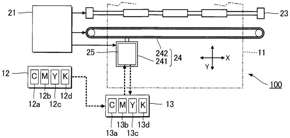
[0047] 1-1. Liquid ejection device 100

[0048] figure 1 It is a schematic diagram illustrating the configuration of the liquid ejection device 100 according to the first embodiment. The liquid ejection device 100 is an inkjet printing device that ejects ink, which is an example of a liquid, as liquid droplets onto the medium 11 . The medium 11 is typically printing paper. However, for example, an object to be printed of any material such as a resin film or cloth may be used as the medium 11 .

[0049]In the liquid ejection device 100, a liquid container 12 storing ink is provided. As the liquid container 12 , for example, an ink cartridge detachable from the liquid ejection device 100 , a pouch-shaped ink pack formed of a flexible film, or an ink tank capable of replenishing ink is used.

[0050] The liquid container 12 includes a first liquid container 12a, a second liquid container 12b, a third liquid container 12c, and a fourth liquid container 12d. The cyan ink C is ...


PUM


Abstract

The invention provides a liquid ejecting apparatus. A first head unit has: a first portion; a second portion connected to the first portion on a first side in the first direction and having a shorterwidth in the second direction than the first portion; and a third portion connected to the first portion on a second side in the first direction, having a shorter width in the second direction, and provided at a position different from the second portion in the second direction. A second head unit has: a fourth portion; a fifth portion connected to the fourth portion on the first side and having ashorter width in the second direction; and a sixth portion connected to the fourth portion on the second side, having a shorter width in the second direction than the fourth portion, and provided ata position different from the fifth portion in the second direction, a portion of the first head, a portion of the second head, a portion of the third head, and a portion of the fourth head being located on the second portion, the third portion, the fifth portion, and the sixth portion, respectively, wherein the first color is blue green and the third color is magenta.

Description

technical field [0001] The present invention relates to a liquid ejection device. Background technique [0002] Patent Document 1 describes a liquid ejection device that ejects liquid such as ink. The liquid ejection device described in Patent Document 1 has a plurality of liquid ejection units as a plurality of head units. Each head unit includes a plurality of heads, specifically, a plurality of drive units. The plurality of heads eject the liquid respectively. Among the plurality of heads, two heads whose positions in the first direction are different from each other are included. The positions of the two heads in the second direction intersecting the first direction are also different from each other. [0003] In a liquid ejection device having a plurality of head units, it may happen that a certain head unit is mounted in a position different from the designed mounting position, for example, after being rotated from the designed mounting position due to a head unit ...

Claims


Application Information

Patent Timeline
Patent Type & Authority Applications(China)
IPC IPC(8): B41J2/14B41J2/145B41J2/21
CPCB41J2/14B41J2/145B41J2/21B41J2/2103B41J2202/19B41J2202/20B41J2/15
Inventor 钟江贵公伊藤伸朗武藤敦史
Owner SEIKO EPSON CORP
Learn More