
Demolding device for mold workpiece machining

A demoulding device and workpiece technology, applied in the direction of manufacturing tools, presses, etc., to achieve the effect of solving the problem of low defect rate, solving bumps, and improving the efficiency of pneumatic demoulding

Active Publication Date: 2021-03-26
河源市华益盛模具有限公司
View PDF7 Cites 0 Cited by
  • Summary
  • Abstract
  • Description
  • Claims
  • Application Information

AI Technical Summary

Problems solved by technology

[0004] Aiming at the deficiencies in the use of the existing demoulding device proposed in the background technology, the present invention provides a demoulding device for processing mold workpieces, which is equipped with pneumatic demoulding so that the force is uniform everywhere on the workpiece, and the air intake on both sides is released. The advantage of reducing the knocking of the mold due to tilting and swaying, solves the technical problems raised in the above-mentioned background technology

Method used


Image

  • Demolding device for mold workpiece machining
  • Demolding device for mold workpiece machining
  • Demolding device for mold workpiece machining

Examples


Embodiment Construction

[0019] The following will clearly and completely describe the technical solutions in the embodiments of the present invention with reference to the accompanying drawings in the embodiments of the present invention. Obviously, the described embodiments are only some, not all, embodiments of the present invention. Based on the embodiments of the present invention, all other embodiments obtained by persons of ordinary skill in the art without making creative efforts belong to the protection scope of the present invention.

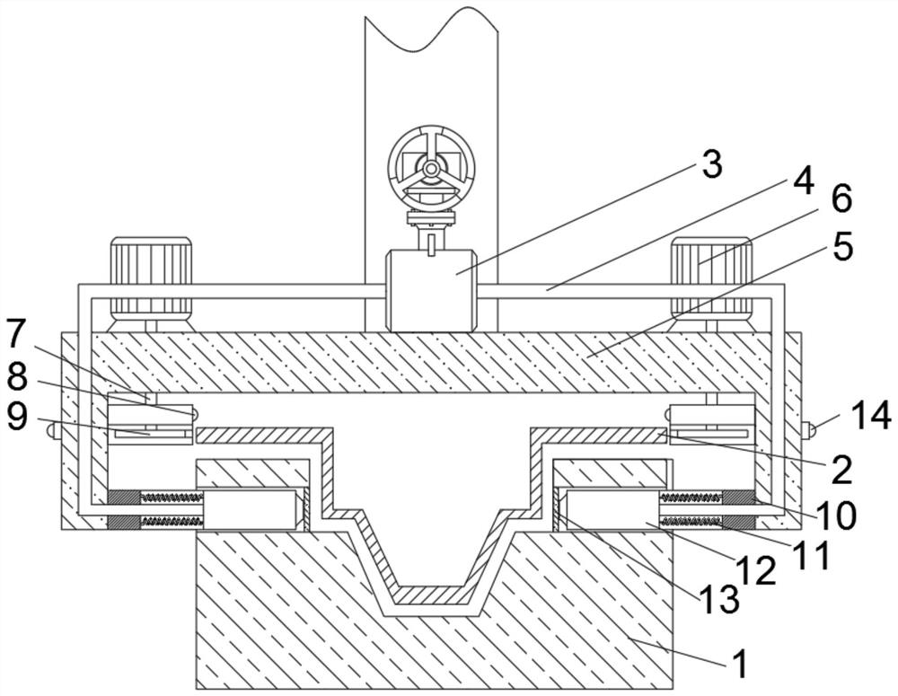
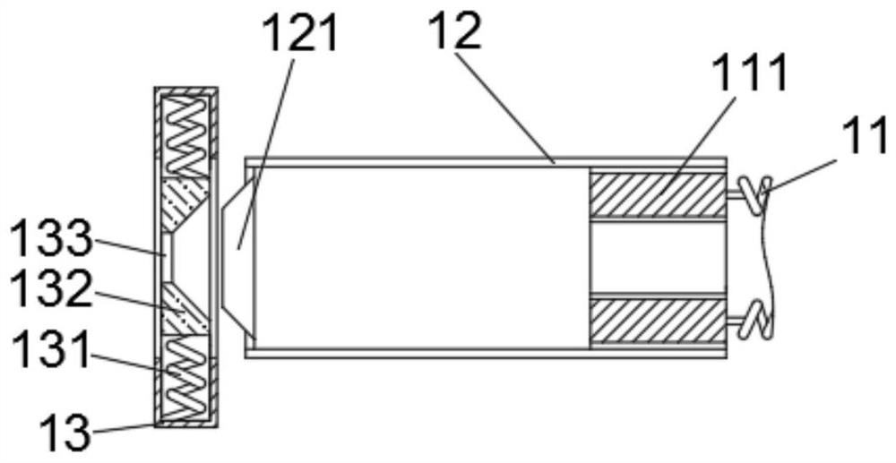
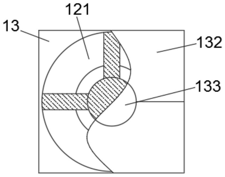
[0020] see Figure 1-5 , a demoulding device for mold workpiece processing, comprising a fixed mold 1, the upper end of the fixed mold 1 is provided with a movable mold 2, the upper end of the movable mold 2 is provided with a cover plate 5, and the upper end of the cover plate 5 is fixedly connected with the air pump 3, the air pump The left and right ends of 3 are connected with two air intake pipes 4, the other ends of the two air intake pipes 4 are fixedly...


PUM


Abstract

The invention relates to the technical field of mold machining, and discloses a demolding device for mold workpiece machining. The demolding device comprises a fixed mold, a movable mold is arranged at the upper end of the fixed mold, a cover plate is arranged at the upper end of the movable mold, the upper end of the cover plate is fixedly connected with an air pump, and the left end and the right end of the air pump are both connected with two air inlet pipes in a penetrating mode. Blowing nozzles are fixedly connected to the other ends of the two air inlet pipes, sliding grooves are slidably connected to the outer walls of the blowing nozzles, magnets are fixedly connected to the right sides of the blowing nozzles, and second springs are fixedly connected to the other ends of the magnets. According to the demolding device for mold workpiece machining, compressed air is guided into the space between the fixed mold and the movable mold through the air pump via the blowing nozzles to achieve pneumatic demolding, and the problem that in the prior art, the defective rate is low due to uneven stress on the surface of a workpiece caused by hoisting or prying is solved; and meanwhile, the workpiece is automatically clamped after demolding is completed through cooperative arrangement of a touch switch, the second springs and a limiting block, and the problem that in the prior art, the workpiece swings and collides due to single-side air inflow is solved.

Description

technical field [0001] The invention relates to the technical field of mold processing, in particular to a demoulding device for mold workpiece processing. Background technique [0002] The mold is to realize the processing of the shape of the object through the cover plate of the physical state of the molding material. It is known as the "mother of industry". Finally, a demoulding process is required to separate the mold from the workpiece. [0003] Most of the existing demoulding devices use the mechanical arm to pull or lift the workpiece by lever, so that the fixed mold and the movable mold form relative motion to realize demoulding. The demoulding method has the following technical defects: First, most of the workpieces to be processed are precision devices and have low rigidity. The demoulding method by clamping, hanging or levering will cause uneven force on the workpiece and cause damage to the device. Damage, serious deformation will cause breakage, and the defect...

Claims


Application Information

Patent Timeline
Patent Type & Authority Applications(China)
IPC IPC(8): B30B15/32
CPCB30B15/32
Inventor 杨慧
Owner 河源市华益盛模具有限公司
Learn More