

Arm restorer for rehabilitation training
A technology of rehabilitation training and recovery device, which is applied in the direction of muscle training equipment, gymnastics equipment, sports accessories, etc. It can solve the problems that affect the exercise of patients and the unfavorable use of the elderly, and achieve the effect of easy change
- Summary
- Abstract
- Description
- Claims
- Application Information
AI Technical Summary
Problems solved by technology
Method used
Image

Examples
Embodiment Construction
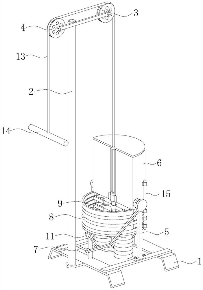
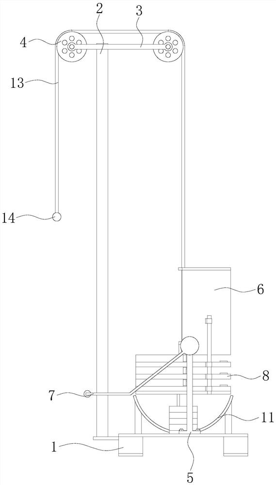
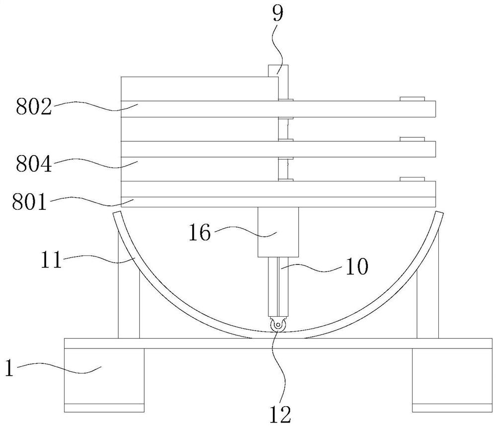
[0028] Such as Figure 1-8 As shown, an arm restorer for rehabilitation training includes a base 1, a vertical bar 2, a horizontal bar 3 and two guide wheels 4, the vertical bar 2 is fixedly connected to the left end of the upper surface of the base 1, and the horizontal bar 3 is connected to the vertical bar 2 The upper end of the base 1 is fixedly connected, and the two guide wheels 4 are respectively mounted on the left and right ends of the cross bar 3, and the front and rear ends of the upper surface of the base 1 are fixedly equipped with support plates 5, and a guide cylinder 6 is arranged between the two support plates 5, The lower end of the guide cylinder 6 is hinged with two support plates 5 respectively, a pedal 7 is fixedly installed at the rotating shaft of the guide cylinder 6 and the support plate 5, and a weight dividing mechanism 8 is fixedly installed on the lower end of the guide cylinder 6, and the weight divider mechanism 8 is connected with the guide The...
PUM
 Abstract
Description
Claims
Application Information