Fast and large dynamic range wavefront detection device and detection method based on pattern recovery

A large dynamic range, wavefront detection technology, applied in the field of optical measurement, can solve the problems of large sampling amount, long calculation time, complicated device construction, etc., to avoid system errors, improve calculation speed, and reduce the amount of calculation.

CN112629677BActive Publication Date: 2022-04-19ZHEJIANG UNIV
11 Cites 0 Cited by

Patent Information

Authority / Receiving Office
CN · China
Patent Type
Patents(China)
Current Assignee / Owner
Publication Date
2022-04-19

Smart Images

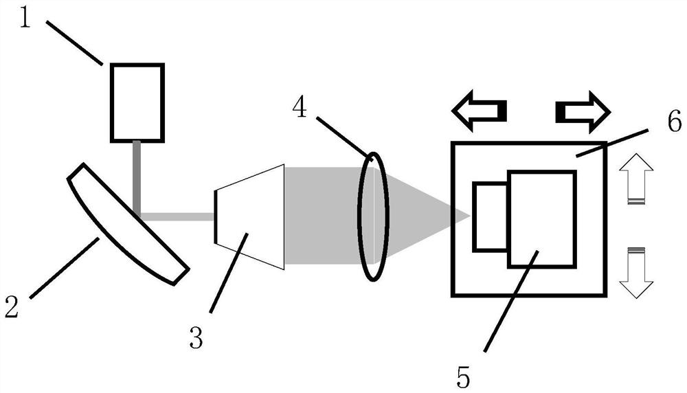
  • Figure 1
    Figure 1
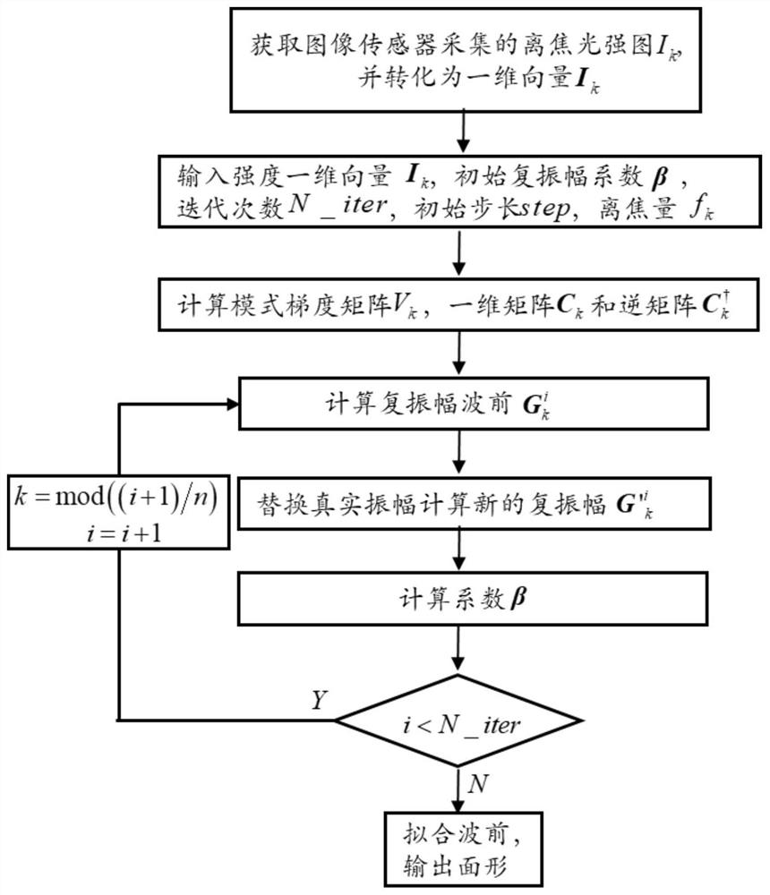
  • Figure 2
    Figure 2
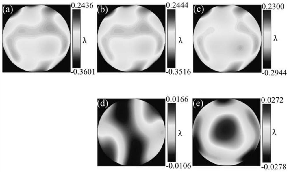
  • Figure 3
    Figure 3
Patent Text Reader

Abstract

The invention discloses a fast large dynamic range wavefront detection device and detection method based on mode restoration. The method replaces the diffraction calculation process with a semi-analytic diffraction base function, and then uses matrix operations between diffraction surfaces to iteratively solve polynomial coefficients. The wavefront detection with high speed and large dynamic range is realized. The device includes a laser, a plano-convex lens, a beam expander, a lens to be tested, and an image sensor arranged in sequence. The present invention calculates the diffraction base function based on the semi-analytic diffraction theory instead of calculating the diffraction transmission process through Fourier transform, realizes the solution of the polynomial coefficients on the diffraction surface through matrix operation, does not need to return to the measurement surface, and can realize fast and accurate wavefront detection with a large dynamic range. The device uses a plano-convex lens instead of a mirror to realize the turning of the light path, which not only realizes the turning of the light path but also attenuates the light intensity. In addition, because the back surface is curved, the reflected light on the back surface does not return to the original light path to avoid interference.
Need to check novelty before this filing date? Find Prior Art

Description

technical field

[0001] The invention relates to the technical field of optical measurement, in particular to a fast and large dynamic range wavefront detection device and detection method based on mode restoration. Background technique

[0002] With the advancement of modern technology, small-diameter grinding and turning tools based on computer control have made it possible to process large-diameter free-form surface components. Large-aperture free-form surface elements are widely used in high-power laser systems such as inertial confinement fusion. Due to the surface defects of the large-diameter optical lens itself and the processing errors left in the grinding process of small-sized processing tools, the wavefront emitted by the large-diameter optical lens is no longer an ideal wavefront. In powerful laser systems, surface errors of optical components can cause distortion of the focus spot, resulting in energy loss and damage to the laser system. Therefore, the detecti...

Examples

Embodiment Construction

[0024] The present invention will be described in detail below with reference to the accompanying drawings and preferred embodiments, and the purpose and effect of the present invention will become clearer. It should be understood that the specific embodiments described here are only used to explain the present invention and are not intended to limit the present invention.

[0025] like figure 1 As shown, the fast large dynamic range wavefront detection device based on mode restoration of the present invention includes a laser transmitter 1, a plano-convex lens 2, a beam expander 3, a lens to be tested 4 and an image sensor 5, along the direction of the forward optical path, The plano-convex lens 2 is located behind the laser emitter 1 with an inclination of 45 degrees, and the plane faces the laser emitter 1. The beam expander 3 and the flat lens to be measured 4 are sequentially arranged behind the plano-convex lens 2, and The plano-convex lens 2, the beam expander 3, the le...