Feeder automation test system

A feeder automation and testing system technology, applied in the field of feeder testing, can solve problems such as system instability, test accuracy deviation, high defect rate of equipment, etc., and achieve accurate test results

Inactive Publication Date: 2021-04-13
THE NORTHERN RES INST OF NJUST
View PDF6 Cites 0 Cited by
  • Summary
  • Abstract
  • Description
  • Claims
  • Application Information

AI Technical Summary

Problems solved by technology

However, in the operation of distribution automation, it is found that there are still problems such as system instability, poor practicality, high equipment defect rate, and low fault location accuracy.
However, the existing automated test technology for feeders generally uses multiple relays to complete simple functional inspections with the support of terminals, master stations and other equipment and equipment suppliers, but the functional inspections in this way ignore fault information and interference data. , the test accuracy is biased, and it is inefficient

Method used


Image

  • Feeder automation test system
  • Feeder automation test system

Examples


Embodiment 1

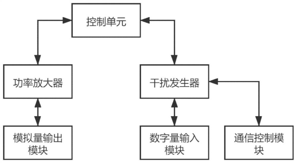
[0022] refer to figure 1 , as the first embodiment of the present invention, a feeder automatic test system is provided, and the feeder automatic test system includes a control unit, a power amplifier and a disturbance generator.

[0023] The control unit is used to complete analog output amplitude and angle control, analog output rectification and communication control, and conduct automatic test of feeder. The power amplifier is used to amplify weak voltage signals into AC current signals and AC voltage signals, and output them through the analog output module. Specifically, the power amplifier is connected to the control unit and the analog output module. The interference generator analyzes and interferes with the signal input to the control unit through the digital input module, and sends the control signal of the control unit through the communication control module. Specifically, the disturbance generator is connected to the control unit, the digital input module and t...

Embodiment 2

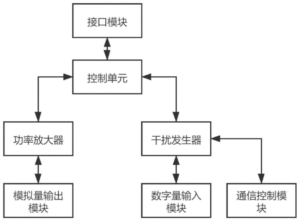
[0027] refer to figure 2 , is the second embodiment of the present invention, and this embodiment is different from the first embodiment in that: the control unit is also connected with an interface module, and the interface module includes a USB interface, a network port and a serial port.

[0028] Compared with Embodiment 1, further, this automatic feeder test system includes a control unit, a power amplifier and an interference generator.

[0029] The control unit is used to complete analog output amplitude and angle control, analog output rectification and communication control, and conduct automatic test of feeder. The power amplifier is used to amplify weak voltage signals into AC current signals and AC voltage signals, and output them through the analog output module. Specifically, the power amplifier is connected to the control unit and the analog output module. The interference generator analyzes and interferes with the signal input to the control unit through the ...


PUM


Abstract

The invention discloses a feeder automation test system which comprises a control unit, a power amplifier and an interference generator. The control unit is used for completing analog quantity output amplitude and angle control, analog quantity output recovery correction and communication control, and carrying out feeder automation testing; and the power amplifier is used for amplifying a weak voltage signal into an alternating current signal and an alternating voltage signal and outputting the alternating current signal and the alternating voltage signal through the analog quantity output module, and the interference generator analyzes and interferes the signal input into the control unit through the digital quantity input module and sends out a control signal of the control unit through the communication control module. Analog quantity output amplitude and angle control, analog quantity output recovery correction and communication control are completed through the control unit, comprehensive and wide feeder automation testing is carried out, fault information and interference data are input through the interference generator, real-time parameter configuration and operation state monitoring are achieved, and a testing result is more accurate.

Description

technical field [0001] The invention relates to the technical field of feeder testing, in particular to a feeder automatic testing system. Background technique [0002] The construction of distribution automation system is being further developed, and has achieved good construction and application results. However, in the operation of distribution automation, it is found that there are still problems such as system instability, poor practicality, high equipment defect rate, and low fault location accuracy. However, the existing automated test technology for feeders generally uses multiple relays to complete simple functional inspections with the support of terminals, master stations and other equipment and equipment suppliers, but the functional inspections in this way ignore fault information and interference data. , the test accuracy is biased and inefficient. Contents of the invention [0003] The purpose of this section is to outline some aspects of embodiments of th...

Claims


Application Information

Patent Timeline
Patent Type & Authority Applications(China)
IPC IPC(8): G01R31/08
CPCG01R31/08
Inventor 朱峰
Owner THE NORTHERN RES INST OF NJUST
Why Eureka
Try Eureka