
Anti-rotation optical lens

An optical lens and anti-rotation technology, applied in the field of optical lenses, can solve problems such as incorrect correction position, eye displacement, unclearness, etc.

Pending Publication Date: 2021-04-20
OPTACT INT
View PDF5 Cites 0 Cited by
  • Summary
  • Abstract
  • Description
  • Claims
  • Application Information

AI Technical Summary

Problems solved by technology

However, in the existing contact lens technology, the structure and shape of the relationship between the inner surface and the eyeball are often only improved, and the improvement of the outer surface is relatively rare.
[0003] The outer surface of the existing contact lens lens is mostly a lens with only a single curvature change or a single thickness change. Therefore, when the user wears it, the contact lens is often pushed by the upper and lower eyelids, or the various reflections of the eyes move by movement
Taking orthokeratology as an example, its purpose is to press the shape of the inner side of the orthokeratology to correct the eyeball. Therefore, it is very important whether the orthokeratology can be placed in a proper position. If the contact lens is between the upper and lower eyelids and the eyeball When the position of the space is not correct, it is obviously impossible to achieve the corrective effect
Taking the general contact lens as an example, its purpose is to change the user's vision to reach the normal range. If the position of the contact lens between the upper and lower eyelids and the eyeball is not correct, it may cause unclear vision or incorrect positioning. corrected position

Method used


Image

  • Anti-rotation optical lens
  • Anti-rotation optical lens
  • Anti-rotation optical lens

Examples


Embodiment Construction

[0038]For the Legate Review Member, the technical characteristics, content and advantages of the present invention, and the effectiveness thereof can be combined with the drawings in accordance with the form of the present invention, and the formula used in the form of the embodiment, Its main purpose is only for the purpose of schematic and the auxiliary instructions. It is not necessarily configured for the implementation of the present invention, so it should not be interpreted on the proportion of the accompanying pattern and the configuration relationship, and the limitation of the scope of the actual implementation , Unite.

[0039]The term "exemplary" will be used in the present invention means that the disclosed components or embodiments are only one example, and no preferences are indicated. In addition, the same numbers indicate the same components in all several icons, and unless otherwise specified in the description, the articles "one" and "above" include a number of inclu...


PUM


Abstract

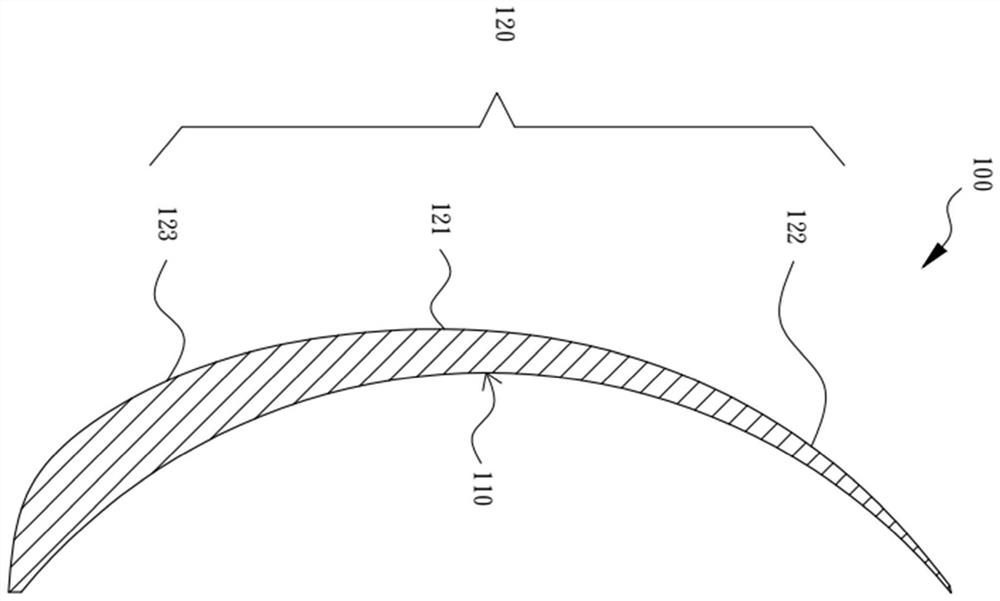
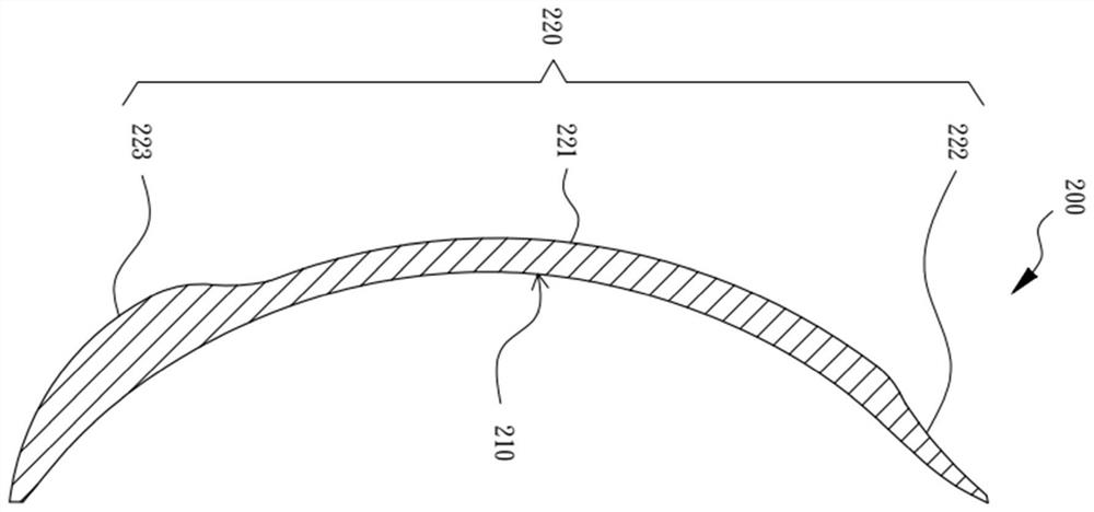
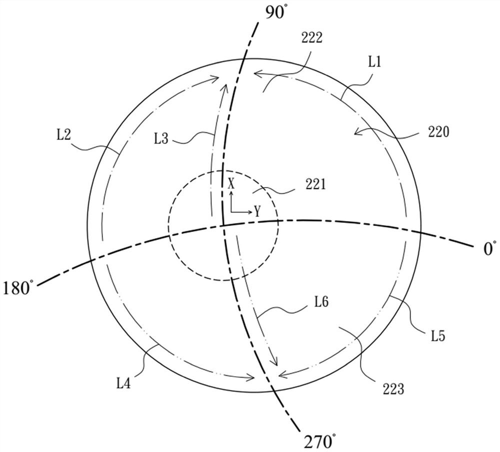
The invention provides an anti-rotation optical lens, which comprises an inner surface and an outer surface, the side, close to an eyeball, of the anti-rotation optical lens is the inner surface, and the other side of the anti-rotation optical lens is the outer surface, the outer surface is provided with an optical part, an adjusting part and a pressing part, wherein the optical part is arranged at a position opposite to an eyeball visible area, and the adjusting part is arranged between the upper portion of the eyeball and the upper eyelid, the pressing part is arranged between the lower portion of the eyeball and the lower eyelid, the thickness of the adjusting part is gradually decreased from one side of the optical part to one side of the adjusting part, and the thickness of the pressing part is gradually increased from the other side of the optical part to one side of the pressing part. According to the anti-rotation optical lens, after blinking by a user for one or more times, the optical part is moved to correspond to a correct wearing position of the eyes through the adjusting part and the pressing part.

Description

Technical field[0001]The present invention relates to an optical lens, in particular to a structural design of a lens, which can move the lens to the correct distribution position of the corresponding eye.Background technique[0002]In the contact lens, whether it is a hard contact lens (RGP), a corneal plastic sheet, an asymptotic dimensional sheet or astigmatic lens, which has an inner surface toward the side of the eye, and the outer surface toward the outside. In the conventional contact lens lens, it is often only necessary to improve the relationship between the inner surface and the eyeball, and the improvement of the outer surface is relatively rare.[0003]The existing outer surface of the existing contact lens is mostly a lens having only a single curvature change, or a single thickness change, so the contact lens is often pushed by the upper and lower eyelids when the user is worn, or various reflections of the eye Action and displacement. Take the corneal plastic sheet as an...

Claims


Application Information

Patent Timeline
IPC IPC(8): G02C7/04G02C7/06
Inventor 周任宇黄美丽
Owner OPTACT INT
Learn More