Door lock structure and cleaning machine applying door lock structure

A door lock structure and keyhole technology, which is applied in the washing machine/washing machine for tableware, application, and parts of the washing machine/rinsing and washing machine for tableware, etc. , prone to failure, etc.

Inactive Publication Date: 2021-05-18
NINGBO FOTILE KITCHEN WARE CO LTD
View PDF5 Cites 0 Cited by
  • Summary
  • Abstract
  • Description
  • Claims
  • Application Information

AI Technical Summary

Problems solved by technology

Although the above structure can lock the door body on the dish washer, its locking structure is complex, highly dependent on...

Method used


Image

  • Door lock structure and cleaning machine applying door lock structure
  • Door lock structure and cleaning machine applying door lock structure
  • Door lock structure and cleaning machine applying door lock structure

Examples


Embodiment 1

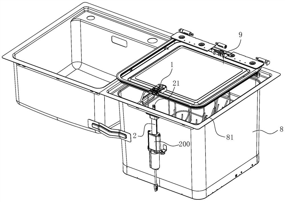
[0044] Such as Figure 1-8 As shown, the door lock structure of this embodiment is used to lock any door body and box body, and this embodiment uses a cleaning machine as an example for illustration. The washing machine of this embodiment comprises a box body 8 and a door body 9, the box body 8 has a washing chamber and an upper port 81 connected to the top of the washing chamber, and an edge of the door body 9 is connected to the edge of the upper port 81 of the box body 8 by rotation place.

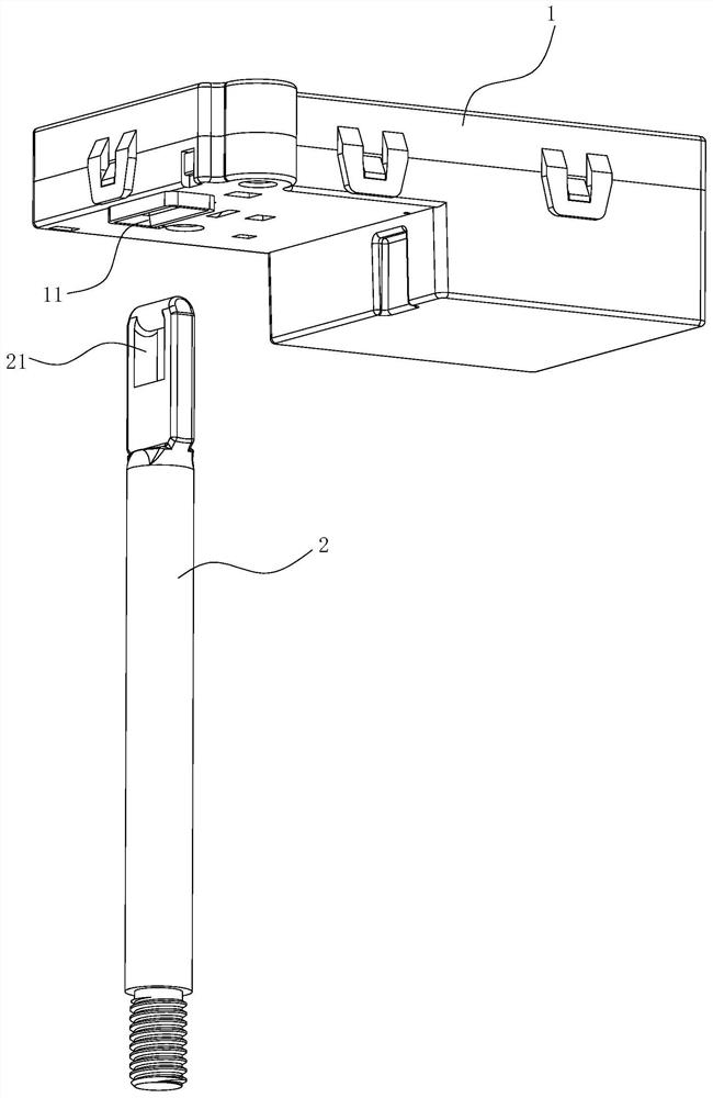
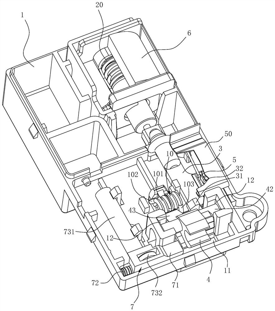
[0045] The door lock structure of this embodiment includes a housing 1 , a push rod 2 , a latch 4 , a first elastic member 10 , a locking plate 3 , a positioning pin 5 , a second elastic member 20 and a driving mechanism 6 . Wherein, the housing 1 is arranged on the door body 9 , and the bottom wall of the housing 1 is provided with a lock hole 11 penetrating up and down. The ejector rod 2 can be moved up and down on the side wall of the box body 1, the upper end of the ejector rod 2 ...

Embodiment 2

[0056] The difference between this embodiment and Embodiment 1 lies in that the structure of the trigger assembly 7 of this embodiment is different from that of Embodiment 1.

[0057] Such as Figure 9As shown, the trigger switch 73' of this embodiment includes a photoelectric module 731' and a shading plate 732', the first end of the shading plate 732' can cooperate with the photoelectric module 731' to form a photoelectric switch, and the second end side of the slider 71' The wall forms a first guide surface 711' that gradually inclines toward the buckle 4 from front to back, and the visor 732' is provided in the housing 1 so that it can move forward and backward, and the side wall at the second end forms a guide surface that can guide with the first guide surface 711'. The matching second guide surface 733', the photoelectric module 731' is disposed at the rear end of the light shielding plate 732'.

[0058] In the state of opening the door, the first end (ie, the rear end...


PUM


Abstract

The invention relates to a door lock structure and a cleaning machine applying the door lock structure. According to the door lock structure, when a door lock needs to be locked, the upper end of an ejector rod moves upwards and is buckled with a lock catch, a driving mechanism drives a locking plate to move backwards and drives a positioning needle to leave the position corresponding to the door opening state in a positioning groove, the restraining effect on the locking plate is cancelled, and the locking plate moves forwards under the action of a second elastic piece and limits the lock catch to prevent the lock catch from turning over, so that the locking state of the lock catch and a locking opening structure on the ejector rod is kept, and locking is completed; when unlocking is needed, the driving mechanism drives the locking plate to move backwards and drives the positioning pin to leave the position corresponding to the door closing state in the positioning groove and to be located at the position corresponding to the door closing state in the positioning groove, at the moment, a limiting structure on the locking plate cancels limiting of the lock catch, the lock catch turns over under the action of a first elastic piece, the lock opening structure of the ejector rod is allowed to be separated from the lock catch, at the moment, the ejector rod can move downwards to exit from a lock hole, and unlocking is completed; and the whole process is simple, reliable and convenient to implement.

Description

technical field [0001] The invention relates to a door lock structure and a washing machine using the door lock structure. Background technique [0002] For a box with a functional inner cavity, due to functional requirements, a door that can open or cover the port is usually provided at the port of the box, and, during the use of the box, it is necessary to place the door relative to the The cabinet is locked. [0003] For example, the Chinese invention patent application "Door Switch Mechanism and Dishwasher with the Door Switch Mechanism" (application publication number: CN1550202A) with application number CN200410043122.5 discloses a structure, which includes: The tableware inlet is configured as a door that can be rotated, and a rotation assist mechanism that applies a rotation assist force to the door along with the rotation of the door; When the door is inside, the door is applied with a rotation assisting force in the direction of closing. Although the above-menti...

Claims


Application Information

Patent Timeline
IPC IPC(8): E05B65/00E05B47/00E05B15/00A47L15/42
CPCA47L15/4259E05B15/00E05B47/0002E05B65/00
Inventor 王式兴朱开杰徐慧
Owner NINGBO FOTILE KITCHEN WARE CO LTD
Why Eureka
Try Eureka