A door lock structure for electrical appliances and a cleaning machine using the door lock structure

A technology of door lock structure and electrical appliances, which is applied in the field of cleaning machines, can solve the problems of low reliability, easy failure, complex door lock action logic, etc., and achieve the effect of easy implementation, simple and reliable process, and low requirements for electric control logic

Active Publication Date: 2022-06-24
NINGBO FOTILE KITCHEN WARE CO LTD
View PDF6 Cites 0 Cited by
  • Summary
  • Abstract
  • Description
  • Claims
  • Application Information

AI Technical Summary

Problems solved by technology

Although the above structure can lock the door body on the dish washer, its locking structure is complex, highly dependent on electric components and control methods, the logic of the door lock action is complicated, prone to failure, and low in reliability

Method used


Image

  • A door lock structure for electrical appliances and a cleaning machine using the door lock structure
  • A door lock structure for electrical appliances and a cleaning machine using the door lock structure
  • A door lock structure for electrical appliances and a cleaning machine using the door lock structure

Examples


Embodiment Construction

[0049] The present invention will be further described in detail below with reference to the embodiments of the accompanying drawings.

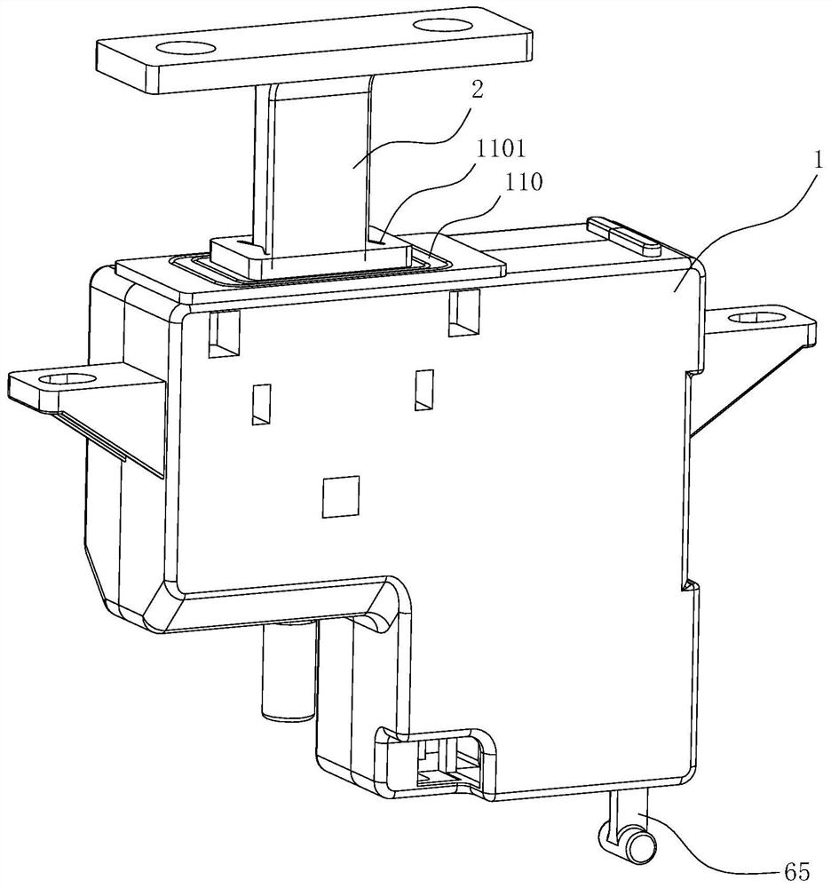
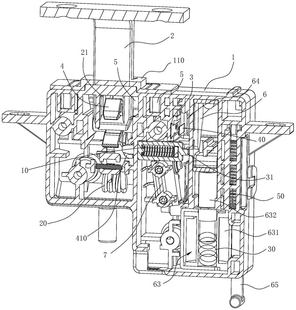
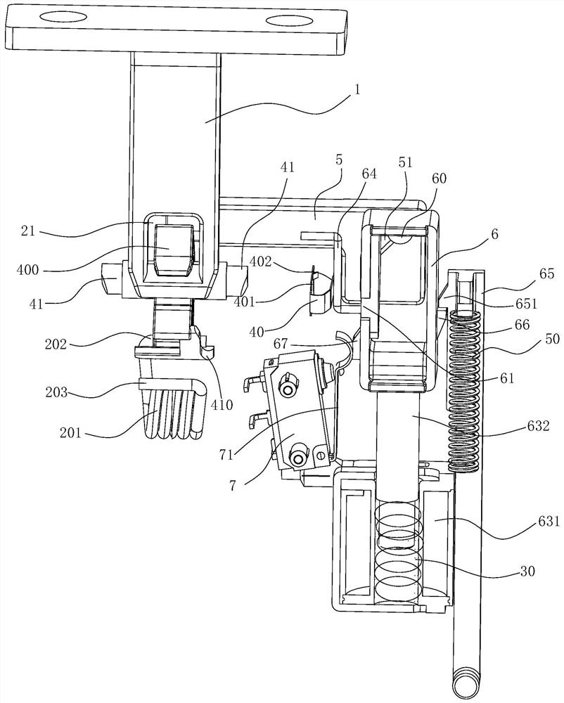
[0050] like Figures 1 to 13 As shown, the door lock structure of this embodiment is used to lock any door body and a box body, and this embodiment is described by taking a sink type washing machine as an example. like Figure 13 As shown, the washing machine of this embodiment includes a box body 8 and a door body 9. The box body 8 has a washing cavity and an upper port 81 connected to the top of the washing cavity. An edge of the door body 9 is rotatably connected to the upper port of the box body 8. 81 at the edge.

[0051] The door lock structure for electrical appliances in this embodiment includes a housing 1, a lock lever 2, a lock catch 4, a second elastic member 20, a stopper 3, a first elastic member 10, an operating member 6, a restricting member 5 and a driving mechanism . The lock lever 2 is vertically installed on the lower ...


PUM


Abstract

The invention relates to a door lock structure for electrical appliances and a cleaning machine using the door lock structure. The door lock structure for electrical appliances includes a housing, a lock bar, a lock buckle, a second elastic member, a stopper, a first An elastic part, an operating part, a restricting part and a driving mechanism. The present invention has low requirements on electric control logic. When locking is required, the lock lever moves down and presses against the lock catch to drive the lock catch to rotate, so that the upper end of the lock catch gradually cooperates with the lock mouth at the lower end of the lock rod to limit each other, and the driving mechanism drives The operating part moves up, and then drives the restricting part to move to the left to limit the position of the buckle, prevent the buckle from turning upwards, and realize locking; when it needs to be unlocked, the driving mechanism drives the operating part to move down, and the restricting part then moves to the right , Cancel the limit on the lock position, at this time, lift the door body upwards, the lock rod can move upwards under the drive of the door body to realize unlocking; the whole process is simple, reliable and easy to realize.

Description

technical field [0001] The invention relates to a door lock structure for electrical appliances and a washing machine applied with the door lock structure. Background technique [0002] For a box with a functional inner cavity, due to functional requirements, a door that can open or cover the port is usually provided at the port of the box, and during the use of the box, the door needs to be relatively The case is locked. [0003] For example, the Chinese invention patent application with the application number CN200410043122.5 "Door switch mechanism and dishwasher with the door switch mechanism" (application publication number: CN1550202A) discloses a structure, which includes: in order to switch on and off the dishwasher A door configured to be rotatable from the cutlery input port, and a rotation assist mechanism that applies a rotation assist force to the door along with the rotation of the door; the rotation assist mechanism extends from a closed state to a predetermin...

Claims


Application Information

Patent Timeline
Patent Type & Authority Patents(China)
IPC IPC(8): E05B47/06E05B15/14A47L15/42
CPCE05B47/0607E05B47/0004E05B15/14A47L15/4259A47L15/4274
Inventor 林益波朱灯光王栋叶芳达
Owner NINGBO FOTILE KITCHEN WARE CO LTD
Why Eureka
Try Eureka