
Prosthesis used for preventing valve reflux

一种瓣膜、假体的技术,应用在阻止瓣膜反流的假体领域,能够解决关闭不全、复杂生理环境、很难匹配等问题,达到阻止瓣膜反流、血液动力学好、减少产品规格的效果

Active Publication Date: 2014-09-24
NINGBO JENSCARE BIOTECHNOLOGY CO LTD
View PDF11 Cites 15 Cited by
  • Summary
  • Abstract
  • Description
  • Claims
  • Application Information

AI Technical Summary

Problems solved by technology

This kind of system is only suitable for the overall repair of the prolapse of the anterior or posterior mitral valve, and the prolapse repair of the whole leaflet of the partial tricuspid valve due to the limitation of the length of the upper part of the native valve annulus, and it shows that the The length of the lower part of the joint body covers at least most of the leaflets, and the joint part has specific arc requirements
This technique cannot adapt to the repair of a small part of the valve prolapse or a small valve such as the aortic valve. When repairing the insufficiency of the valve, the rest of the normal valve is sacrificed at the same time.
To sum up, its disadvantages include: first, it is clearly described that the length of the upper part of the joint body is equal to the distance between the first and second commissures, so it is only suitable for the overall repair of the leaflets, and the repair area includes both Leaf prolapse also includes the normal part of the leaflet; second, the length of the valve annulus varies greatly from person to person, and the distance between the first and second commissures before the actual operation is unpredictable The design is precisely matched; third, the shape of the joint body is conical, trying to match the conical shape of the human valve leaflet, and it is also difficult to completely match due to human differences; fourth, the design is not suitable for combined valve leaflet prolapse repair
The main reason is that the mitral valve ring and tricuspid valve ring have special physiological structures, and there is a complex physiological environment below the valve ring, making it very difficult to accurately position and fix the product
In addition, the degree and location of valve prolapse are different. For example, some patients have regurgitation caused by anterior valve prolapse, and some patients have regurgitation caused by combined valve disease. It also interferes with the physiological structure of the remaining normal mitral valve, and the adaptability of the lesion is insufficient

Method used


Image

  • Prosthesis used for preventing valve reflux
  • Prosthesis used for preventing valve reflux
  • Prosthesis used for preventing valve reflux

Examples


specific Embodiment 1

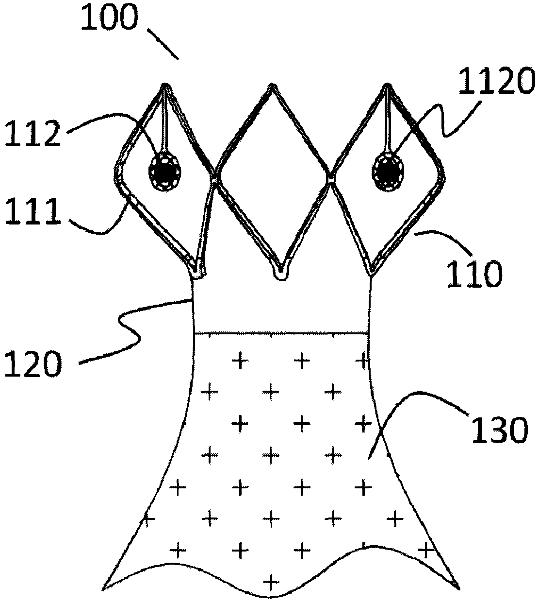
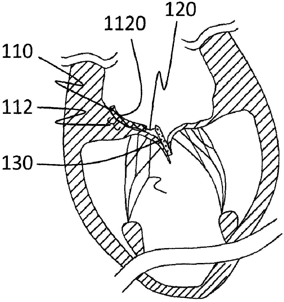
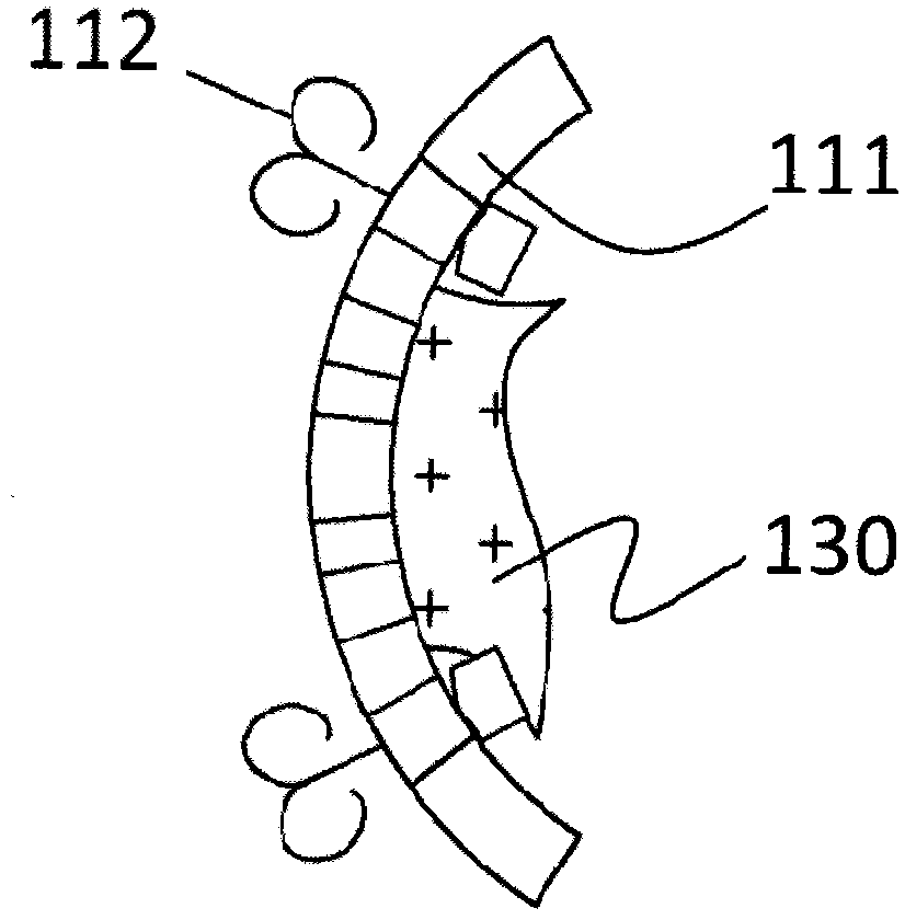
[0067] Such as Figure 1a and Figure 1b As shown, a prosthesis 100 for preventing valve regurgitation includes a fixing unit 110, a connecting member 120 and an auxiliary member 130, the fixing unit 110 includes a fixing member 111 and at least two anchoring members 112, the The distal part of the connecting part 120 is connected with the proximal part of the fixing part 110, the proximal part of the connecting part 120 is connected with the distal part of the closing aid 130, and the connecting part 120 is flexible, so that The connecting member 120 and the closing aid 130 connected thereto can move along with the movement of the leaflets, and there is a channel for blood to flow between the closing aid 130 and the fixing member 111 , so The fixing part 111 is a polymer sheet or the fixing part 111 has a skeleton structure, the fixing part 111 is fixed on the patient's atrium wall or valve annulus through the anchor part 112, and the width of the fixing part 111 expanded Le...

specific Embodiment 2

[0070] Such as Figure 4a and Figure 4b As shown, a prosthesis 200 for preventing valvular regurgitation includes a fixing unit 210, a connecting member 220, and an auxiliary member 230. The fixing unit 210 includes a fixing member 211 and at least two anchoring members 212. The distal part of the connecting part 220 is connected with the proximal part of the fixing part 210, the proximal part of the connecting part 220 is connected with the distal part of the closing aid 230, and the connecting part 220 is flexible, so that The connecting member 220 and the closing aid 230 connected thereto can move along with the movement of the leaflets, and there is a channel for blood to flow between the closing aid 230 and the fixing member 211 , so The fixing part 211 is a polymer mesh cloth or the fixing part 211 has a skeleton structure, the fixing part 211 is fixed on the patient's atrium wall or valve annulus through the anchor part 212, and the fixing part 211 is expanded The wi...

specific Embodiment 3

[0074] Such as Figure 8a and Figure 8b As shown, a prosthesis 300 for preventing valve regurgitation includes a fixing unit 310, a connecting member 320 and an auxiliary member 330. The fixing unit 310 includes a fixing member 311 and at least two anchoring members 312. The distal part of the connecting part 320 is connected with the proximal part of the fixing part 310, the proximal part of the connecting part 320 is connected with the distal part of the closing aid 330, and the connecting part 320 is flexible, so that The connecting member 320 and the closing assisting member 330 connected thereto can move along with the movement of the leaflets, and there is a channel for blood to flow between the closing assisting member 330 and the fixing member 311 , so The fixing part 311 is a polymer sheet or the fixing part 311 has a skeleton structure, the fixing part 311 is fixed on the patient's atrium wall or valve annulus through the anchor part 312, and the expanded width of ...


PUM


Abstract

The invention relates to a prosthesis (100) used for preventing valve reflux. The prosthesis comprises a fixing unit (110), a connecting piece (120) and a closing assisting piece (130). The fixing unit (110) comprises a fixing piece (111) and an anchoring piece (112). The connecting piece (120) is flexible. The far end portion of the connecting piece (120) is connected with the near end portion of the fixing piece (110). The near end portion of the connecting piece (120) is connected with the far end portion of the closing assisting piece (130). The fixing piece (111) is fixed to the atrium wall or the valve ring of a patient through the anchoring piece (112). The width of the unfolded fixing piece (111) is smaller than two thirds the perimeter of the valve tissue ring. The closing assisting piece (130) is located between the autologous valve leaflets of the patient when the closing assisting piece (130) is in the free state. The maximum width of the closing assisting piece (130) is smaller than the maximum width of a single unfolded autologous valve leaflet. The near end of the anchoring piece (112) is provided with an anti-disengagement end (1120). The prosthesis is adjustable in position, accurate in positioning, capable of being firmly anchored and not prone to adhering to tissue near the valve ring of the patient.

Description

Technical field: [0001] The invention belongs to the field of medical devices, and in particular relates to a prosthesis for preventing valvular regurgitation. Background technique: [0002] The mitral valve is located at the left atrioventricular orifice and consists of five parts: the valve annulus, valve leaflets, chordae, papillary muscles, and junctional junction. Its anatomically accurate name is mitral apparatus (mitral apparatus) or mitral valve compound body (mitral complex). [0003] The tricuspid valve is located at the right atrioventricular orifice and has three approximately triangular sail-shaped valves. The bottom of the valve is attached to the fibrous annulus of the atrioventricular orifice. Functionally, the fibrous annulus, valves, chordae and papillary muscles can be seen. It is a tricuspid valve. Valve complex (tricuspid valvar complex). [0004] Mitral regurgitation (mitral regurgitation) can be divided into the following two types: 1. Rheumatic card...

Claims


Application Information

Patent Timeline
Patent Type & Authority Applications(China)
IPC IPC(8): A61F2/24
CPCA61F2/246A61F2002/8483A61F2002/8486A61F2210/0014A61F2220/0016A61F2220/0025A61F2250/0004A61F2/2445
Inventor 李毅斌吕世文徐志云李佳楠郑德源陈志
Owner NINGBO JENSCARE BIOTECHNOLOGY CO LTD
Learn More