Method for reducing dynamic power dissipation and electronic device

A technology of dynamic power consumption and electronic equipment, applied in the direction of reducing energy consumption, electrical components, data processing power supply, etc., can solve the problems of large logic circuit optimization gating, the gating effect is not obvious, and the power consumption saving benefit is not obvious. , to avoid extra burden and reduce dynamic power consumption

Inactive Publication Date: 2012-05-02
HUAWEI TECH CO LTD
View PDF6 Cites 16 Cited by
  • Summary
  • Abstract
  • Description
  • Claims
  • Application Information

AI Technical Summary

Problems solved by technology

[0008] This method of reducing dynamic power consumption uses a synthesis tool to automatically enter and exit the gate control unit according to the logic function. In the actual implementation process, only a small part of the circuit in the chip or programmable device can be optimized for gate control, and there is no way for large logic The circuit is optimized for gating, so the overall gating effect is not obvious, and the power saving benefit is not obvious

Method used


Image

  • Method for reducing dynamic power dissipation and electronic device
  • Method for reducing dynamic power dissipation and electronic device
  • Method for reducing dynamic power dissipation and electronic device

Examples


Embodiment Construction

[0027] The following will clearly and completely describe the technical solutions in the embodiments of the present invention with reference to the accompanying drawings in the embodiments of the present invention. Obviously, the described embodiments are only some, not all, embodiments of the present invention. Based on the embodiments of the present invention, all other embodiments obtained by persons of ordinary skill in the art without creative efforts fall within the protection scope of the present invention.

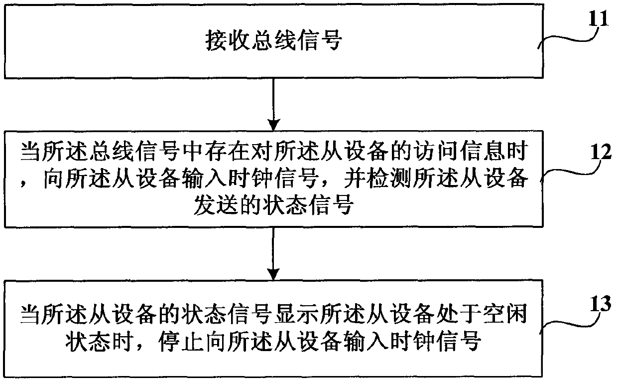
[0028] figure 1 It is a flowchart of a method for reducing dynamic power consumption provided by an embodiment of the present invention. Such as figure 1 As shown, methods to reduce dynamic power consumption include:

[0029] Step 11, receiving the bus signal.

[0030] Among them, the bus signal (bus-signal) is a general term for a combination of multiple bus signals, including HADDR[31:0] and HTRANS[1] of the AMBA2.0 bus, using HADDR[31:0] and HTRANS[1] signals...


PUM


Abstract

The present invention relates to a method for reducing a dynamic power dissipation and an electronic device. The method is used to reduce the dynamic power dissipation of a slave unit, and comprises the steps of receiving a bus signal when access information of the slave unit is existed in the bus signal; inputting a clock signal to the slave unit and detecting a state signal sent by the slave unit; when the state signal of the slave unit displays that the slave unit is located in a free state, stopping inputting the clock signal to the slave unit. In the invention, by controlling work clocks of chip inner device modules, such as the slave unit, etc. via the bus signal and the slave unit, the chip inner device module is avoided from generating an unnecessary circuit turnover under a non-work state, to thereby achieve the purpose of reducing the dynamic power dissipation of the chip inner device module.

Description

technical field [0001] The invention relates to an energy-saving technology of an equipment module in a chip, in particular to a method for reducing dynamic power consumption and electronic equipment. Background technique [0002] With the application and development of wireless chips, reducing chip power consumption has become an increasingly urgent requirement. [0003] Wherein, the power consumption of the chip includes static power consumption and dynamic power consumption. [0004] For example, the bus architecture based on AMBA2.0AHB includes three parts: bus (AHBLocalBus), master module and slave module. The master device module and the slave device module can be devices such as IP cores, chips, or functional modules, and are all connected to the AMBA bus. The dynamic power savings of the master and slave modules depends on the ability to shut down the internal logic of these devices when not in use. [0005] A method to reduce the power consumption of master-slave...

Claims


Application Information

Patent Timeline
Patent Type & Authority Applications(China)
IPC IPC(8): G06F1/32
CPCG06F1/3237G06F1/32G06F1/325H03L5/02G06F1/266Y02B60/32Y02D10/00Y02D30/50
Inventor 周勇辉余剑锋
Owner HUAWEI TECH CO LTD
Why Eureka
Try Eureka