Touch Sensor Detector System and Method

a detector system and sensor technology, applied in the field of systems and methods, can solve problems such as the accuracy with which a single touch can be tracked, and achieve the effects of high tracking resolution, increased sensor performance, and high resolution

Active Publication Date: 2015-04-02
SENSEL
View PDF1 Cites 21 Cited by
  • Summary
  • Abstract
  • Description
  • Claims
  • Application Information

AI Technical Summary

Benefits of technology

[0045]In some preferred invention embodiments, the present invention may be applied to the creation of a low-cost, multi-touch, high resolution, force sensing touch sensor that can be manufactured using traditional PCB manufacturing methods as well as additive printing techniques. The present invention utilizes the concept of an interpolating array which allows a high tracking resolution without requiring a large number of drive and sense lines to be connected to the sensor scan electronics (active lines). By increasing the tracking resolution relative to the number of active drive and sense lines, the present invention allows for increased sensor performance with reduced electronics complexity and cost as compared to other sensor technologies. Herein are described several possible embodiments for the sensor and how it can be adapted to different use cases such as stylus interaction and embedding below or over a display.
[0046]In one preferred interpolating force sensing array (IFSA) embodiment, the present invention addresses deficiencies in the prior art by adding a network of resistors to the inputs and outputs of a force sensing array which decouples

Problems solved by technology

Interestingly, the resolution of the drive and sense circuitry only has an effect on the distance at which two distinct touches start

Method used


Image

  • Touch Sensor Detector System and Method
  • Touch Sensor Detector System and Method
  • Touch Sensor Detector System and Method

Examples


embodiment (

IFSA Embodiment (3300)-(6400)

Overview

[0225]While the present invention may be implemented using a wide variety of sensor technologies in the VIA, one preferred collection of exemplary embodiments utilize pressure-sensitive sensors to form an interpolating force sensing array (IFSA). The following discussion details this pressure-sensitive class of preferred embodiments and provides detailed exemplary construction contexts. Note that while the IFSA embodiments are detailed below, the techniques used in their construction may be equally applied to other types of sensor technologies such as capacitive, electromagnetic, etc.

[0226]In accordance with the above general description, the present invention IFSA embodiment describes systems and methods for constructing a high resolution force sensing array, an interpolating circuit that allows the drive and sense circuitry to have a lower resolution than the force sensing array, a circuit and accompanying algorithms for scanning the sensor and...


PUM


Abstract

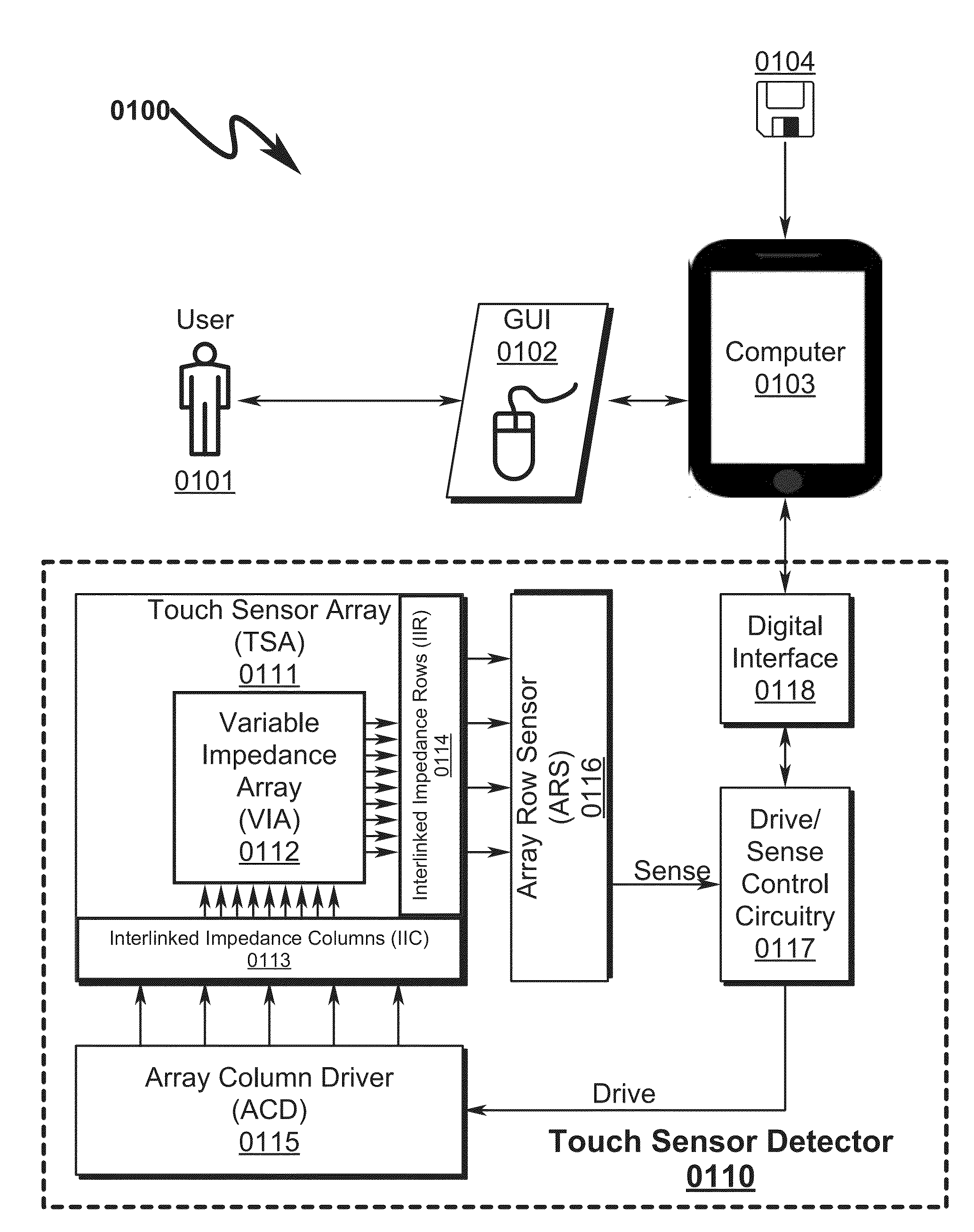
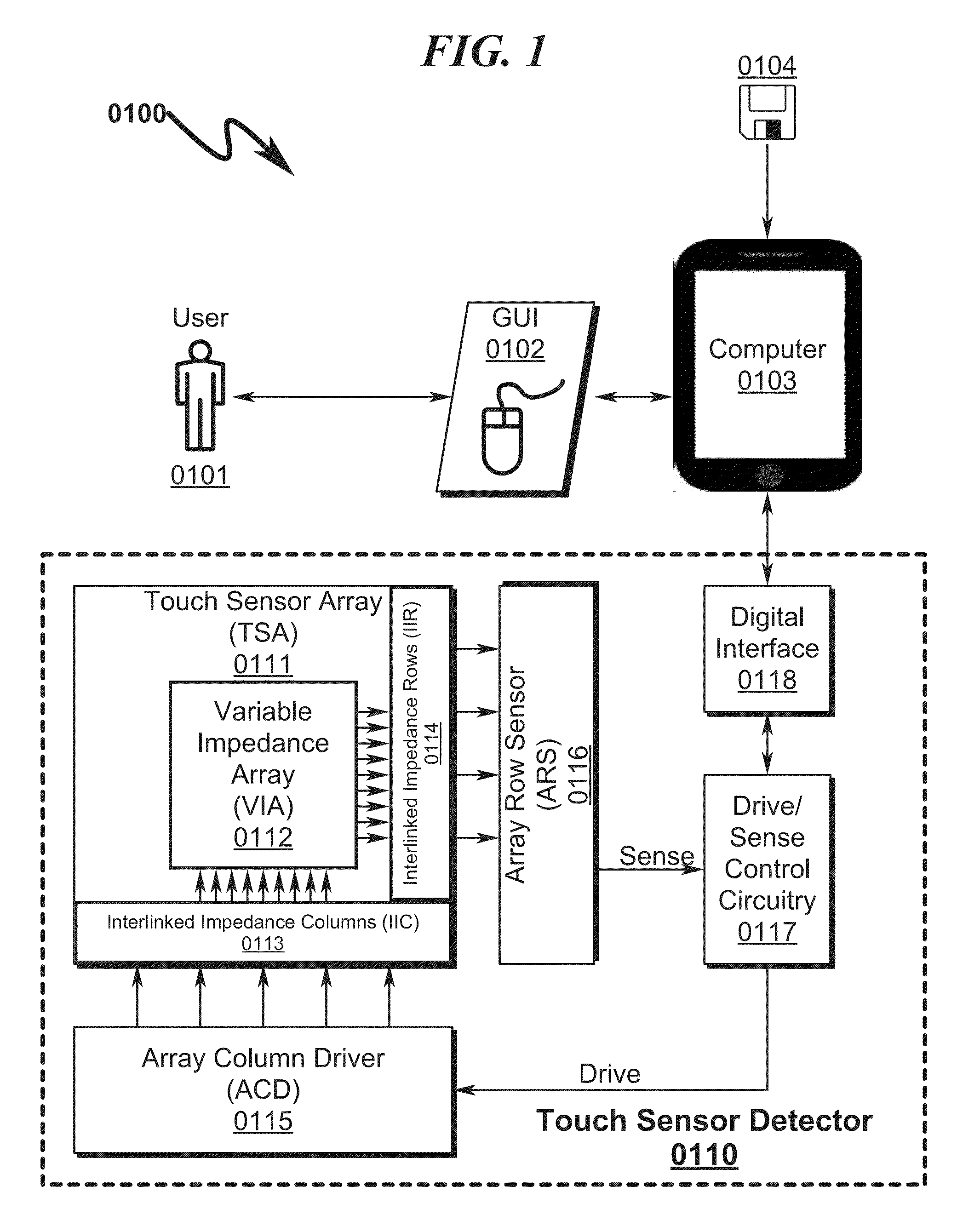
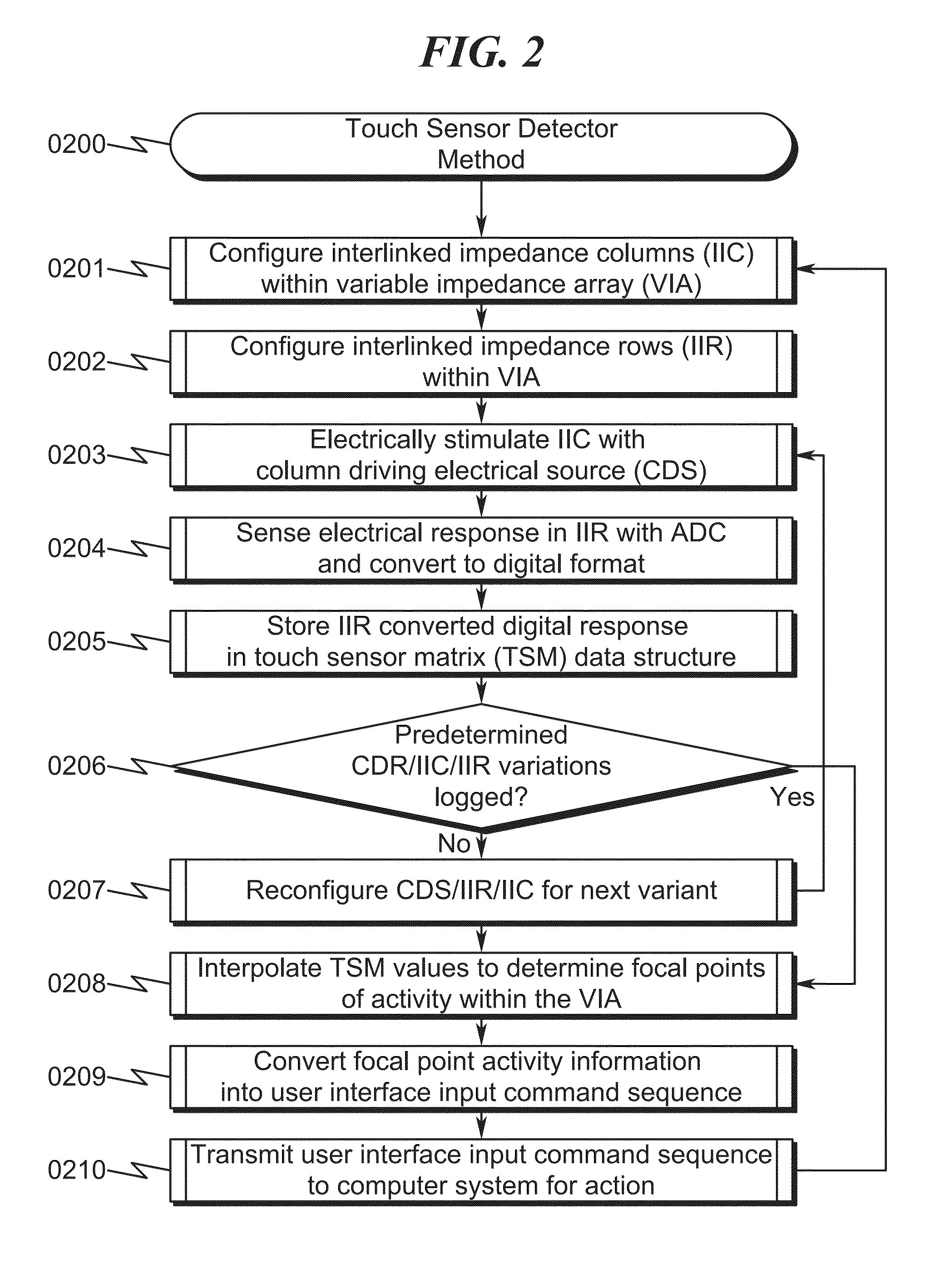
A touch sensor detector system and method incorporating an interpolated sensor array is disclosed. The system and method utilize a touch sensor array (TSA) configured to detect proximity/contact/pressure (PCP) via a variable impedance array (VIA) electrically coupling interlinked impedance columns (IIC) coupled to an array column driver (ACD), and interlinked impedance rows (IIR) coupled to an array row sensor (ARS). The ACD is configured to select the IIC based on a column switching register (CSR) and electrically drive the IIC using a column driving source (CDS). The VIA conveys current from the driven IIC to the IIC sensed by the ARS. The ARS selects the IIR within the TSA and electrically senses the IIR state based on a row switching register (RSR). Interpolation of ARS sensed current/voltage allows accurate detection of TSA PCP and/or spatial location.

Description

CROSS REFERENCE TO RELATED APPLICATIONSContinuation Patent Application (CPA)[0001]This is a continuation patent application (CPA) of and incorporates by reference U.S. Utility patent application for TOUCH SENSOR DETECTOR SYSTEM AND METHOD by inventors Ilya Daniel Rosenberg and John Aaron Zarraga, filed electronically with the USPTO on Jun. 25, 2014, with Ser. No. 14 / 314,662, EFSID 19410170, confirmation number 8306, docket JSENS.00002.Utility Patent Applications[0002]This application claims benefit under 35 U.S.C. §120 and incorporates by reference U.S. Utility patent application for TOUCH SENSOR DETECTOR SYSTEM AND METHOD by inventors Ilya Daniel Rosenberg and John Aaron Zarraga, filed electronically with the USPTO on Jun. 25, 2014, with Ser. No. 14 / 314,662, EFSID 19410170, confirmation number 8306, docket JSENS.00002.Provisional Patent Applications[0003]This application claims benefit under 35 U.S.C. §119 and incorporates by reference U.S. Provisional Patent Application for INTERP...

Claims


Application Information

Patent Timeline
IPC IPC(8): G06F3/044
CPCG06F2203/04104G06F3/044G06F3/04144G06F3/04166G06F3/041661G06F3/0442G06F3/0443G06F3/0445G06F3/0446G06F2203/04103G06F2203/04106G06F3/045
Inventor ROSENBERG, ILYA DANIELZARRAGA, JOHN AARON
Owner SENSEL
Why Eureka
Try Eureka