A door lock structure and a washing machine using the door lock structure

A door lock structure and locking technology, which is applied in the washing machine/rinsing machine of tableware, application, parts of washing machine/rinsing and washing machine of tableware, etc., which can solve the problem of lax door closing, door lock device, etc. problems, to achieve the effect of easy operation, high reliability, and low requirements for electronic control logic

Active Publication Date: 2022-01-25
NINGBO FOTILE KITCHEN WARE CO LTD
View PDF9 Cites 0 Cited by
  • Summary
  • Abstract
  • Description
  • Claims
  • Application Information

AI Technical Summary

Problems solved by technology

[0005] But this door lock device has the risk that the door is not tightly closed, because when the latch is inserted to make the door in the closed state, the door lock spring is in a compressed state, and in the closed state, the latch is in contact with the door lock switch lever, and the force of the spring It will be transmitted to the bolt so that the bolt has a tendency to move away from the door lock sensing support, and because the two sides of the door lock bolt have rounded bosses, the door lock bolt can be pulled out after an external force is applied, and the force applied by the spring Even if the force is not enough to make the door lock pin come out completely, there is still a tendency to make the lock pin move out of the door lock sensing support, resulting in the possibility of the door not being tightly closed.

Method used


Image

  • A door lock structure and a washing machine using the door lock structure
  • A door lock structure and a washing machine using the door lock structure
  • A door lock structure and a washing machine using the door lock structure

Examples


Embodiment Construction

[0050] The present invention will be further described in detail below in conjunction with the accompanying drawings and embodiments.

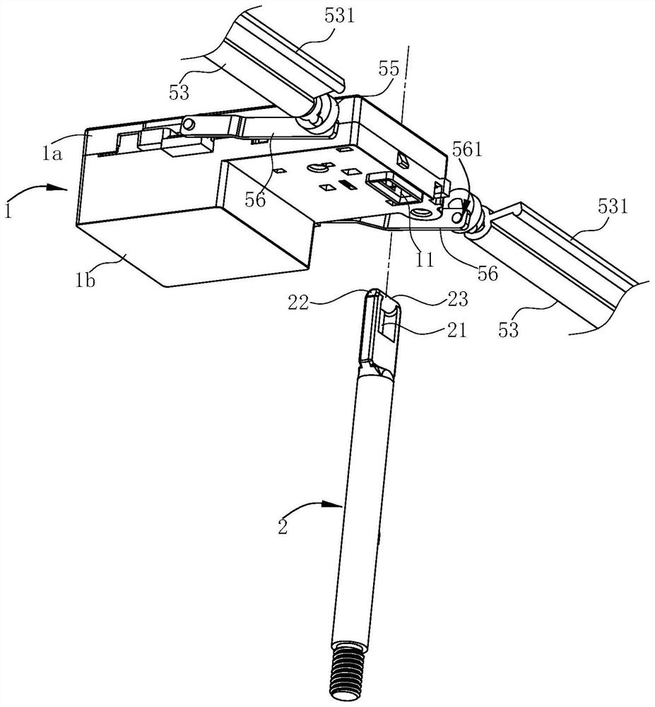
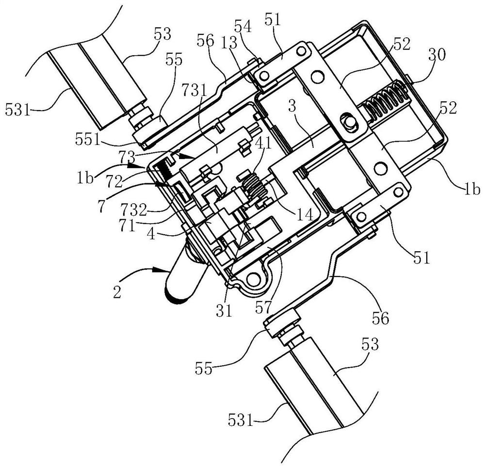
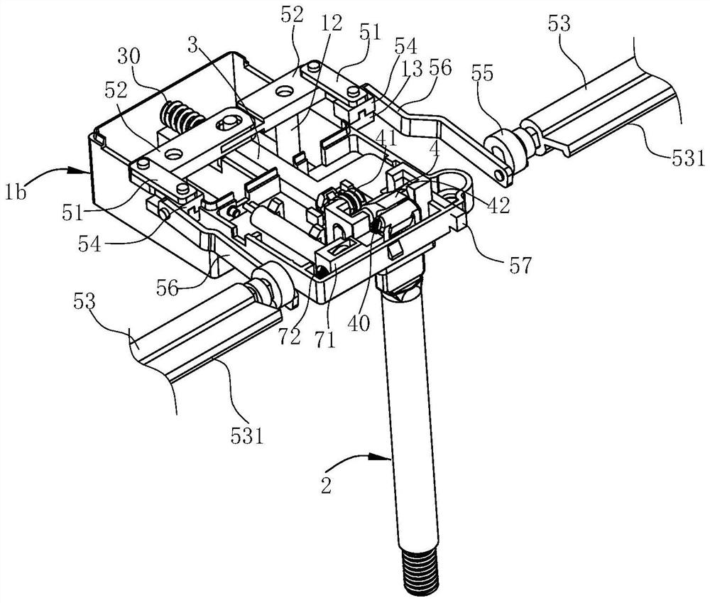
[0051] Such as Figure 1-10 As shown, the door lock structure of this embodiment is used to lock any door body and box body, and this embodiment takes a washing machine (such as a dishwasher) as an example for illustration. The washing machine of this embodiment comprises a box body 8 and a door body 9, the box body 8 has a washing chamber and an upper port 81 connected to the top of the washing chamber, and an edge of the door body 9 is connected to the edge of the upper port 81 of the box body 8 by rotation place.

[0052] The door lock structure of this embodiment includes a housing 1 , a push rod 2 , a latch 4 , a first elastic member 41 , a locking plate 3 , a second elastic member 30 , a driving mechanism, a driving assembly 20 and a trigger assembly 7 . Wherein, the housing 1 is arranged on the door body 9, and the housing 1 is compos...


PUM


Abstract

The invention relates to a door lock structure and a cleaning machine using the door lock structure, wherein the door lock structure includes a housing with a lock hole; Mouth, the top of the ejector rod above the lock opening is columnar; the lock, which is rotatably arranged in the housing and above the lock hole, has a locking groove, which can limit the top of the ejector rod in it and lock the ejector rod Locking; the first elastic member keeps the locking groove downward; the locking plate is set in the housing so that it can move back and forth relative to the lock hole, and a limiting structure is arranged between the locking plate and the lock catch; the second elastic The locking plate keeps the tendency of moving forward; the driving mechanism is used to drive the locking plate to move backward against the elastic force of the second elastic piece, so that the locked state of the lock catch and the push rod is released. The door lock structure has low dependence on electric control logic.

Description

technical field [0001] The invention relates to a door lock structure and a washing machine using the door lock structure. Background technique [0002] For a box with a functional inner cavity, due to functional requirements, a door that can open or cover the port is usually provided at the port of the box, and, during the use of the box, it is necessary to place the door relative to the The cabinet is locked. [0003] For example, the Chinese invention patent application "Door Switch Mechanism and Dishwasher with the Door Switch Mechanism" (application publication number: CN1550202A) with application number CN200410043122.5 discloses a structure, which includes: The tableware inlet is configured as a door that can be rotated, and a rotation assist mechanism that applies a rotation assist force to the door along with the rotation of the door; When the door is inside, the door is applied with a rotation assisting force in the direction of closing. Although the above-menti...

Claims


Application Information

Patent Timeline
Patent Type & Authority Patents(China)
IPC IPC(8): A47L15/42E05B65/00
CPCA47L15/4259E05B65/00
Inventor 朱开杰王式兴
Owner NINGBO FOTILE KITCHEN WARE CO LTD
Why Eureka
Try Eureka