
A high-efficiency and energy-saving down filling machine

A high-efficiency energy-saving down filling machine technology, applied in the field of down filling machines, can solve the problems of lack of internal down breaking device, unfavorable quality of load-bearing products, and easy agglomeration of down, so as to improve economic benefits and better quality , better quality results

Active Publication Date: 2021-11-09
东至南意服装厂
View PDF4 Cites 0 Cited by
  • Summary
  • Abstract
  • Description
  • Claims
  • Application Information

AI Technical Summary

Problems solved by technology

[0003] In the interior of the existing down filling machine, there is a lack of a corresponding internal fluff breaking device, so that the internal fluff is easy to agglomerate during the production and compression process, which is not conducive to the subsequent load-bearing and the realization of the uniform quality of the product

Method used


Image

  • A high-efficiency and energy-saving down filling machine
  • A high-efficiency and energy-saving down filling machine
  • A high-efficiency and energy-saving down filling machine

Examples


Embodiment 1

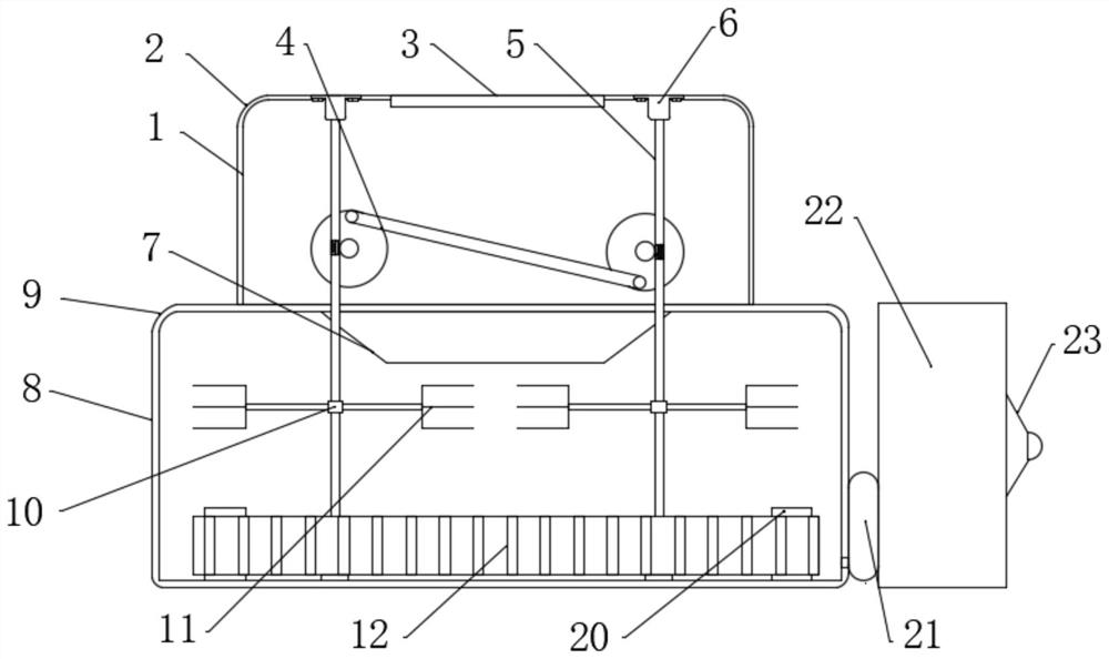
[0030] see Figure 1~4 , in an embodiment of the present invention, a high-efficiency and energy-saving down filling machine includes a top cover 1, and the inside of the top cover 1 is used for installing a device for initially processing down down. Top cover 1 is provided with top fillet 2 around the peripheral part, and the top of the middle part of top cover 1 is provided with feeding hole 3, and the middle part of top cover 1 is internally rotated and installed with breaking device 4, and the effect of breaking up device 4 is Fluff the fluff directly inside the unit. The side parts of the breaking device 4 are engaged with a longitudinal rod device 5, and the effect of the longitudinal rod device 5 is to realize the linkage of the bottom auxiliary device. A mounting plate 6 is fixedly installed on the top of the longitudinal rod device 5 , and the mounting plate 6 is a fixing device for the longitudinal rod device 5 . The bottom of the middle part of the top cover 1 is ...

Embodiment 2

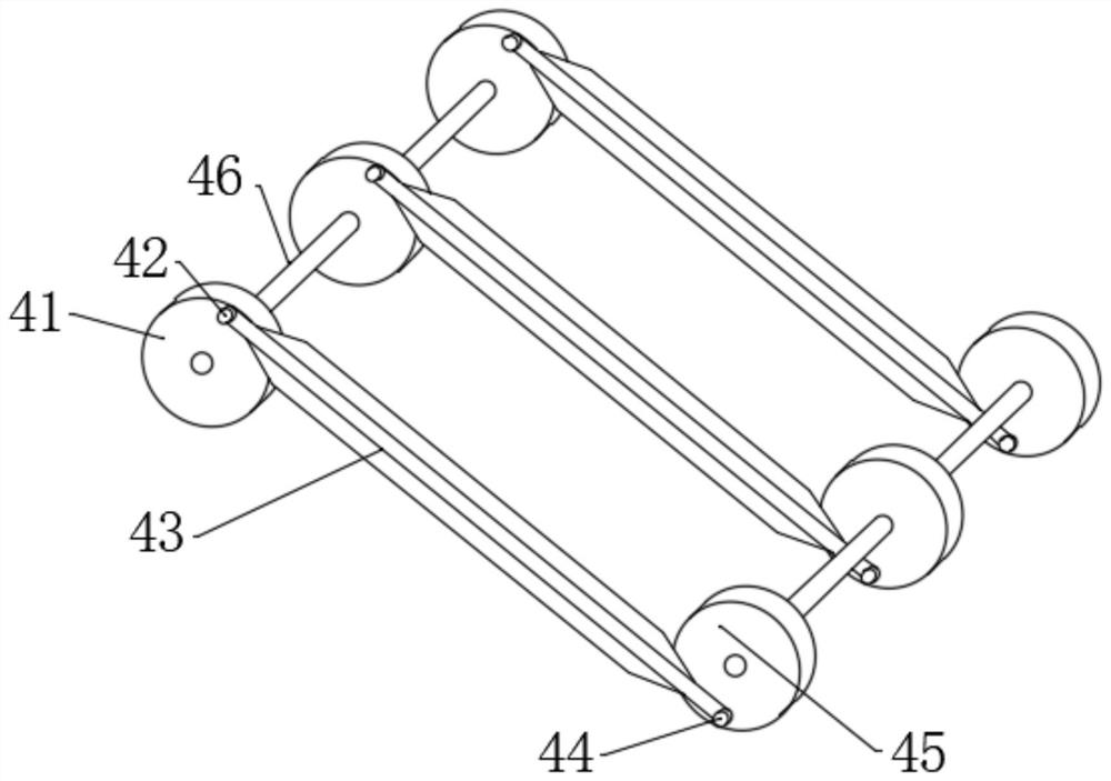
[0035] see Figure 5-6 The difference between this embodiment of the present invention and Embodiment 1 is that the conveying device 12 includes a roller shaft 121 fixedly installed at the bottom of the bottom cover 8 at the side, and a belt 122 is sleeved on the surface of the roller shaft 121. The belt 122 The inner ring of the belt 122 is fixedly equipped with an internal flange 123, and the outer surface of the belt 122 is fixedly equipped with an external flange 124, and the effect of the flange is exactly to transmit fluff.

[0036] The rear part of the middle part of the turntable 41 is fixedly equipped with an insert shaft 24 , the surface of the insert shaft 24 is fixedly equipped with bevel teeth 25 , and the side parts of the bevel teeth 25 are meshed with engaging bevel teeth 26 .

[0037] The meshing bevel teeth 26 are plugged and installed on the surface of the longitudinal bar device 5 .

[0038] The working principle of the present invention is:

[0039] When t...


PUM


Abstract

The invention discloses a high-efficiency and energy-saving down filling machine, which relates to the field of down filling machines and mainly aims to solve the problem of breaking down down; There is a feed hole on the top, a breaking device is installed in the middle part of the top cover, and a longitudinal rod device is installed on the side part of the breaking device. A funnel is fixedly installed at the bottom, a connecting bearing is fixedly installed at the bottom of the middle part of the longitudinal rod device, an auxiliary breaking device is fixedly installed at the end of the connecting bearing, and a transmission device is installed at the bottom of the longitudinal rod device. The parts are plugged with installation shafts, the side parts tail of the bottom cover are fixedly equipped with an air pump, the tail part of the air pump is plugged with a tail collecting bin, and the side parts of the tail collecting bin are fixedly equipped with a spout.

Description

technical field [0001] The invention relates to the field of down filling machines, in particular to a highly efficient and energy-saving down filling machine. Background technique [0002] Down filling machine, a kind of light industrial equipment that can be used for commercial purposes and garment industry. It is a machine that uses a high-pressure fan to absorb fillings such as down and chemical fibers, and fills down jackets, duvets and other clothing products. Down filling machines mostly use stainless steel shells to make them look elegant, clean and durable, and the down filling machines only use fans when they work, which consumes little power. It is suitable to be used as a filling and selling equipment for duvets in stores, and can also be used as a large-scale factory production line. Now there are still some down filling machines. In order to facilitate the introduction of down quilts, down filling machines have added down light boxes and voice commentary func...

Claims


Application Information

Patent Timeline
Patent Type & Authority Patents(China)
IPC IPC(8): A41H43/00B68G7/06
CPCA41H43/00B68G7/06
Inventor 刘象华
Owner 东至南意服装厂
Learn More