Area-controlled flue gas distributor and boiler system

A distributor and flue gas technology, which is applied in exhaust gas devices, combustion product treatment, combustion methods, etc., can solve the problems of increasing flue gas resistance, dust removal effect, heat waste, etc. The effect of the uniform temperature of the flue gas at the outlet and the effect of improving the heat exchange effect

Active Publication Date: 2021-06-11
SHANDONG ELECTRIC POWER ENG CONSULTING INST CORP
View PDF5 Cites 1 Cited by
  • Summary
  • Abstract
  • Description
  • Claims
  • Application Information

AI Technical Summary

Problems solved by technology

If the flue gas temperature deviation is large, the flue gas temperature of some runners is lower than the original design value, and the flue gas temperature of some runners is higher than the original design value
If the flue gas temperature is lower than the design value of the flue gas temperature at the inlet of the low-temperature economizer, the heat exchange area of ​​the low-temperature economizer in the flow channel will be excessive, resulting in waste. If the design value is the same, the low-temperature economizer on this flow channel cannot be put into operation, that is, the flue gas resistance is increased, and the economic benefits in terms of heat have not yet been obtained
If the flue gas temperature is higher than the design value of the flue gas temperature at the inlet of the low-temperature economizer, the heat exchange area of ​​the low-temperature economizer in the flow channel will be insufficient. Although there will be some margin in the selection of the low-temperature economizer, but If the flue gas temperature exceeds the design value too much, the flue gas temperature at the outlet of the low-temperature economizer will not be reduced to the designed flue gas temperature at the outlet of the low-temperature economizer, resulting in waste of heat
[0006] The heat transfer area of ​​the low-temperature economizer on each channel is the same, and the inlet flue gas temperature is different. In order to achieve the same outlet flue gas temperature, the condensate flow rate of each low-temperature economizer must be different. Each low-temperature economizer There is also a regulating valve on the water pipeline of the coal boiler, which brings difficulties to the operation and regulation
The temperature at the inlet of the low-temperature economizer is deviated, while the temperature at the outlet of the low-temperature economizer is the same, which will aggravate the deviation of the actual flue gas volume of each channel, resulting in the deviation of the flue gas volume in each channel of the dust collector, which has a great impact on dust removal effect

Method used


Image

  • Area-controlled flue gas distributor and boiler system
  • Area-controlled flue gas distributor and boiler system
  • Area-controlled flue gas distributor and boiler system

Examples


Embodiment 1

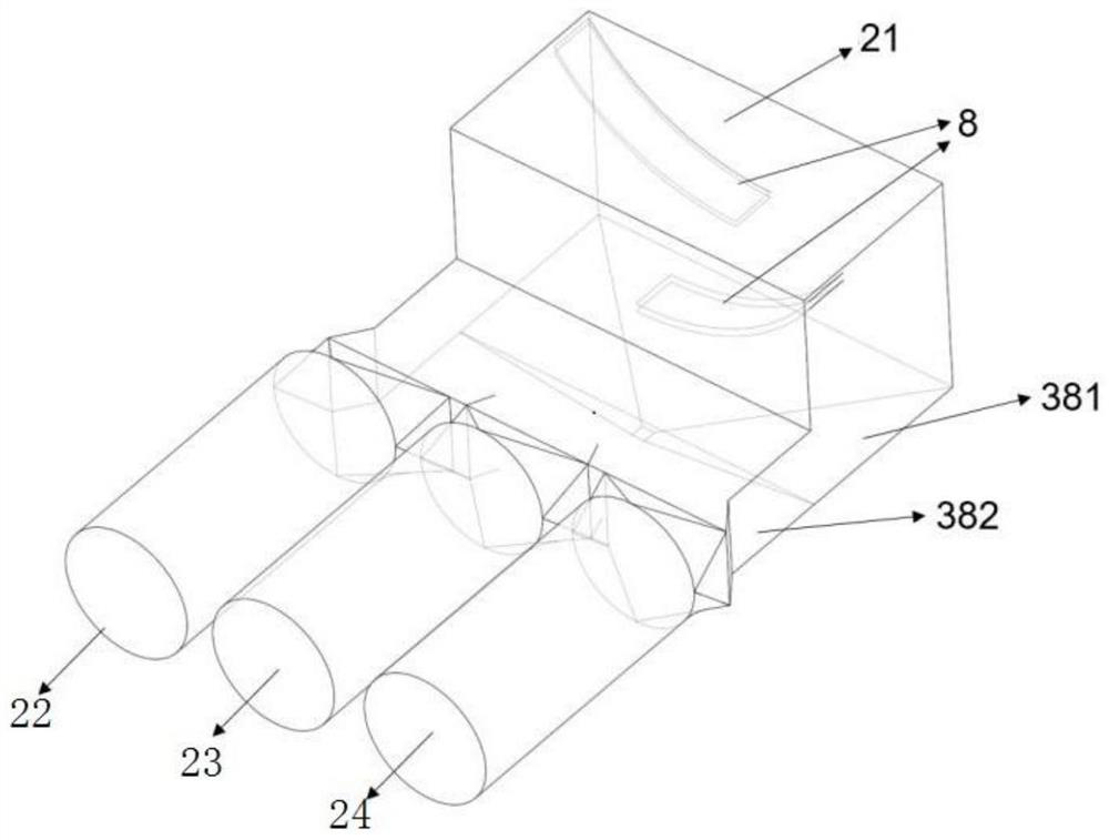
[0042] This embodiment provides a smoke distributor with area control, such as image 3 As shown, the smoke distributor 38 of this embodiment is an L-shaped structure, including a vertical part 381 and a horizontal part 382, ​​one end of the vertical part 381 communicates with one end of the horizontal part 382, ​​and the other end is the smoke inlet 21; the horizontal part 382 The other end is divided into multiple flue gas outlets.

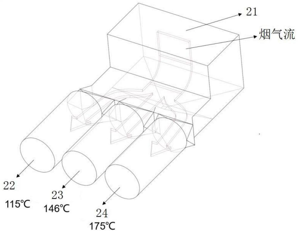
[0043] In this embodiment, there are three flue gas outlets, namely the first flue gas outlet 22 , the second flue gas outlet 23 , and the third flue gas outlet 24 . Preferably, both the vertical portion 381 and the horizontal portion 382 are rectangular in cross-section.

[0044] Due to the different flue gas temperatures at different positions in the flue, there is a problem of uneven flue gas temperature distribution in the three flue gas outlets connected to the tail of the flue gas distributor 38, such as figure 2 As shown, the temperatu...

Embodiment 2

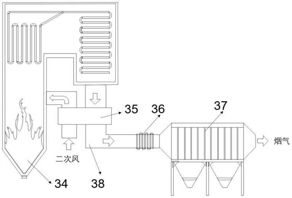
[0074] This embodiment provides a boiler system, such asfigure 1 As shown, it includes a boiler 34, the top of the boiler 34 is provided with a flue gas outlet, and the flue gas outlet is connected to the flue, and an air preheater 35, a low-temperature economizer 36 and a dust collector 37 are arranged in sequence in the flue, wherein the air preheater 35 and the low-temperature The flue gas distributor 38 described in Embodiment 1 is arranged between the economizers 36 .

[0075] Further, the flue gas distributor 38 is connected to the low-temperature economizer 36 through the non-metallic expansion joint 33 , and the flue gas flows through the low-temperature economizer 36 to heat the return water and then enters the dust collector 37 . The ash hopper connection flange 1 of the flue gas distributor 38 is connected to the non-metallic compensator at the outlet of the air preheater 35 .

[0076] During operation, pulverized coal burns in the furnace to produce flue gas, and t...


PUM


Abstract

The invention discloses an area-controlled flue gas distributor and a boiler system. According to the technical scheme, the area-controlled flue gas distributor is characterized in that a plurality of flow guide plates are arranged in the flue gas distributor in a staggered mode, each flow guide plate comprises a fixed flow guide plate body and an adjustable flow guide plate body, and the adjustable flow guide plate bodies are connected with a driving mechanism; and under the action of the driving mechanism, the adjustable flow guide plate bodies can stretch out or retract by a set distance relative to the fixed flow guide plate bodies so as to change the areas of the flow guide plates. According to the flue gas distributor, by arranging the adjustable flow guide plate bodies, the areas of the flow guide plates can be increased or reduced according to actual requirements, so that the flue gas mixing degree and the resistance are adjusted, and different actual heat conduction requirements are met; and the heat exchange requirement is further met, and the service life of a product is prolonged.

Description

technical field [0001] The invention relates to the field of heat exchangers, in particular to an area-controlled flue gas distributor and a boiler system. Background technique [0002] The L-shaped flue gas distributor is a common equipment for the outlet flue of the air preheater. It is used to evenly divide the flue gas at the flue gas side outlet of the air preheater, reduce the flue gas flow rate at the inlet of a single dust collector, and improve the dust removal efficiency. Arranging low-temperature economizers at the outlet of the distributor and the inlet of the dust collector can further reduce the exhaust gas temperature, improve boiler efficiency, and reduce pollutant emissions. The performance of the distributor is of great significance to the stable and efficient operation of thermal power units, energy saving and emission reduction. The flue gas flow rate, ash volume and temperature uniformity of the branch flue downstream of the distributor are important in...

Claims


Application Information

Patent Timeline
Patent Type & Authority Applications(China)
IPC IPC(8): F23J15/00F23J13/00
CPCF23J15/006F23J13/00Y02E20/34
Inventor 曹洪振祁金胜张斌程鹏辛公明杜文静李官鹏蒋莉王妮妮
Owner SHANDONG ELECTRIC POWER ENG CONSULTING INST CORP
Why Eureka
Try Eureka