Vacuum suction cup

A technology of vacuum suction cups and suction cups, applied in the direction of clamping, supporting, positioning devices, etc., can solve problems such as difficult clamping and easy deformation, and achieve the effect of reducing the area

Active Publication Date: 2018-07-10
北京海普瑞森超精密技术有限公司
View PDF7 Cites 1 Cited by
  • Summary
  • Abstract
  • Description
  • Claims
  • Application Information

AI Technical Summary

Problems solved by technology

[0002] In mechanical processing, because the disc parts of the lathe are prone to deformation during processing, it is difficult to clamp, and the sizes of the disc parts are different, so our commonly used ring groove vacuum suction cups can meet the flexible, convenient, fast and fast processing of the parts. High precision, but not suitable for disk parts with different sizes, the ring groove vacuum chuck can meet the flexible, convenient and fast clamping of parts

Method used


Image

  • Vacuum suction cup
  • Vacuum suction cup
  • Vacuum suction cup

Examples


Embodiment Construction

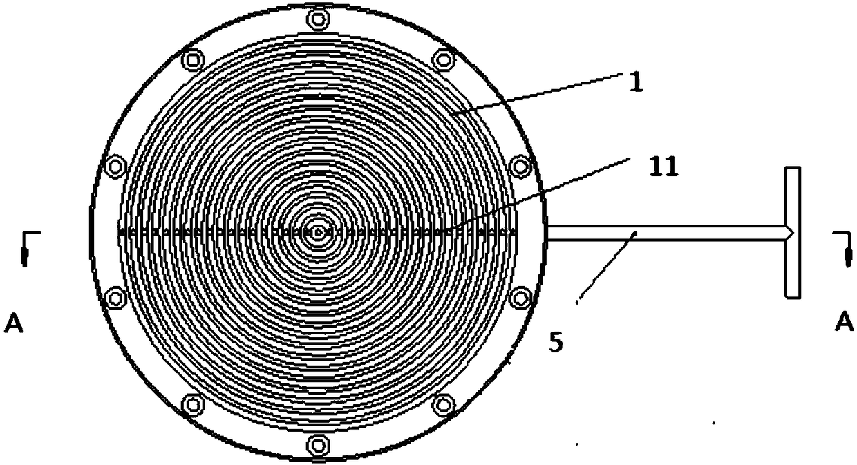
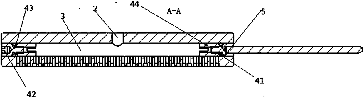
[0021] The present invention will be further described below in conjunction with the accompanying drawings and embodiments. However, the use and purpose of these exemplary embodiments are only used to exemplify the present invention, and do not constitute any form of limitation to the actual protection scope of the present invention, let alone limit the protection scope of the present invention thereto.

[0022] Some orientation words are defined in the present invention. In the case of no contrary description, the orientation words used such as "up, down, left, and right" refer to the definition of the vacuum chuck provided by the present invention under normal use conditions, And it is consistent with the up, down, left, and right directions shown in the accompanying drawings. "Inside and outside" refer to inside and outside relative to the outline of each part itself. These orientation words are adopted for easy understanding, and thus do not constitute a limitation to the...


PUM


Abstract

The invention discloses a vacuum sucker. A plurality of circular grooves are formed in the front end face of the vacuum sucker; through holes are formed in the bottom ends of the circular grooves; a first through hole is formed in the axial center of the vacuum sucker; a second through hole is formed in the radial direction of the vacuum sucker; the second through hole communicates with the through holes; and sucker plugs are arranged in the second through hole. When the vacuum sucker provided by the invention is used for clamping disc parts with different sizes, a vacuum sucker area adjusting mechanism has the advantage of flexibly, conveniently and quickly adjusting the clamping area of the vacuum sucker according to the sizes of the parts during use.

Description

technical field [0001] The invention relates to the field of mechanical automation production machines, in particular to a vacuum chuck that is mostly used in the high-precision numerical control machine tool industry. Background technique [0002] In mechanical processing, because the disc parts of the lathe are prone to deformation during processing, it is difficult to clamp, and the sizes of the disc parts are different, so our commonly used ring groove vacuum suction cups can meet the flexible, convenient, fast and fast processing of the parts. The precision is high, but it cannot satisfy the flexible, convenient and fast clamping of the parts when the disc parts are of different sizes. Contents of the invention [0003] The purpose of the present invention is to provide a vacuum suction cup, which can solve the technical problem of flexible, convenient and fast clamping of the parts when the disc parts are of different sizes. [0004] In order to achieve the above ob...

Claims


Application Information

Patent Timeline
Patent Type & Authority Patents(China)
IPC IPC(8): B23Q3/00
CPCB23Q3/00B23Q2703/04
Inventor 黄云忠荣德志赵建强焦尚才
Owner 北京海普瑞森超精密技术有限公司
Why Eureka
Try Eureka