
Apparatus for carrying chemical tracers on downhole tubulars, wellscreens, and the like

a technology of chemical tracer and apparatus, which is applied in the direction of survey, borehole/well accessories, construction, etc., can solve the problems of limiting the type of chemical tracer that can be used, damage to tracer materials, and increase costs

Inactive Publication Date: 2019-02-26
WEATHERFORD TECH HLDG LLC
View PDF46 Cites 1 Cited by
  • Summary
  • Abstract
  • Description
  • Claims
  • Application Information

AI Technical Summary

Benefits of technology

This patent describes a device that allows for the placement of tracer elements on a wellscreen joint in a flexible and customizable way. The device allows for the adjustment of the open area of the screen through the use of holes in a shroud, which can be composed of plate metal or pipe. The device can also be added after assembly, allowing for the adjustment of the isotope formulation for the tracer material and accommodation of changes in well design. The device is designed to remove the risk of damage to the tracer elements during screen fabrication and to facilitate the installation process.

Problems solved by technology

In general, typical wellscreen designs require that the tracer elements be incorporated in the screen during the screen manufacturing process, which increases costs and limits which type of chemical tracer can be used.
This is difficult due to the limited space between the shroud and the metal mesh.
The tracer materials can be heat sensitive and may be exposed to welding / heat treatment operations during manufacturing that can damage the tracer materials.
Because these techniques require specific pre- and post-assembly steps, the ability to configure a screen with a tracer in the field is limited.
This reduces the opportunity to make any changes to the well design program.
Another problem is that current screen constructions might limit the amount of tracer that can be installed on the screen.

Method used


Image

  • Apparatus for carrying chemical tracers on downhole tubulars, wellscreens, and the like
  • Apparatus for carrying chemical tracers on downhole tubulars, wellscreens, and the like
  • Apparatus for carrying chemical tracers on downhole tubulars, wellscreens, and the like

Examples


Embodiment Construction

[0051]Embodiments of the present disclosure can be used with joints without screen or joints with screens. For example, embodiments of the present disclosure can be used with completion screen joints in a completion, such as generally depicted in FIG. 1, although other arrangements can be used.

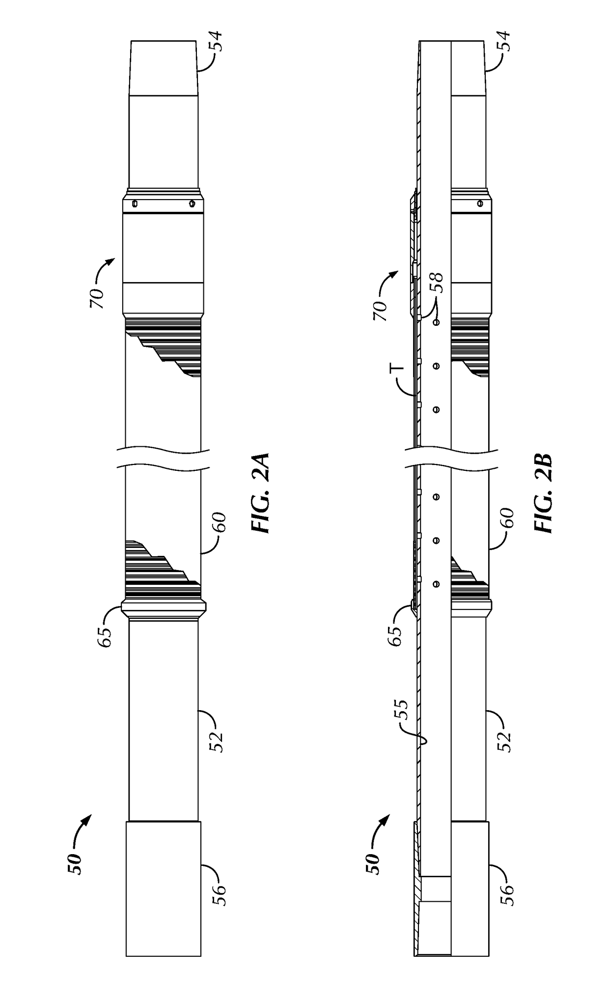
[0052]Turning now to FIGS. 2A-2C, a completion screen joint 50 is shown in a side view, a partial side cross-sectional view, and a detailed view, showing placement of tracer elements T. The screen joint 50 has a basepipe 52 with a sand control jacket 60 and an access device 70 disposed thereon. The basepipe 52 defines a through-bore 55 and has a coupling crossover 56 at one end for connecting to another joint or the like. The other end 54 can connect to a crossover or coupling (not shown) of another joint on the completion string. Inside the through-bore 55, the basepipe 52 defines pipe ports 58, which can be defined along the length of the basepipe 52 where the screen jacket 60 is located. Ad...


PUM


Abstract

An access device installs on a wellscreen joint during manufacture and allows access to one or more spaces or layers where tracer elements can be installed adjacent the joint's screen jacket (i.e., internal and / or external to the screen jacket). Portion of the access device is removable to allow installation of the tracer elements after the joint has been manufactured. With the tracer elements installed, the access device can be reassembled and locked in place. Any various mechanism can allow the access device to be partially removed, the tracer elements to be installed, and the access device to be reassembled in place. For example, an end ring holding the jacket on the basepipe can have at least one channel communicating with a space or layer for insertion of the tracer elements. A removable cover can be removed to allow access to the at least one channel and can be reattached for the wellscreen to be used downhole.

Description

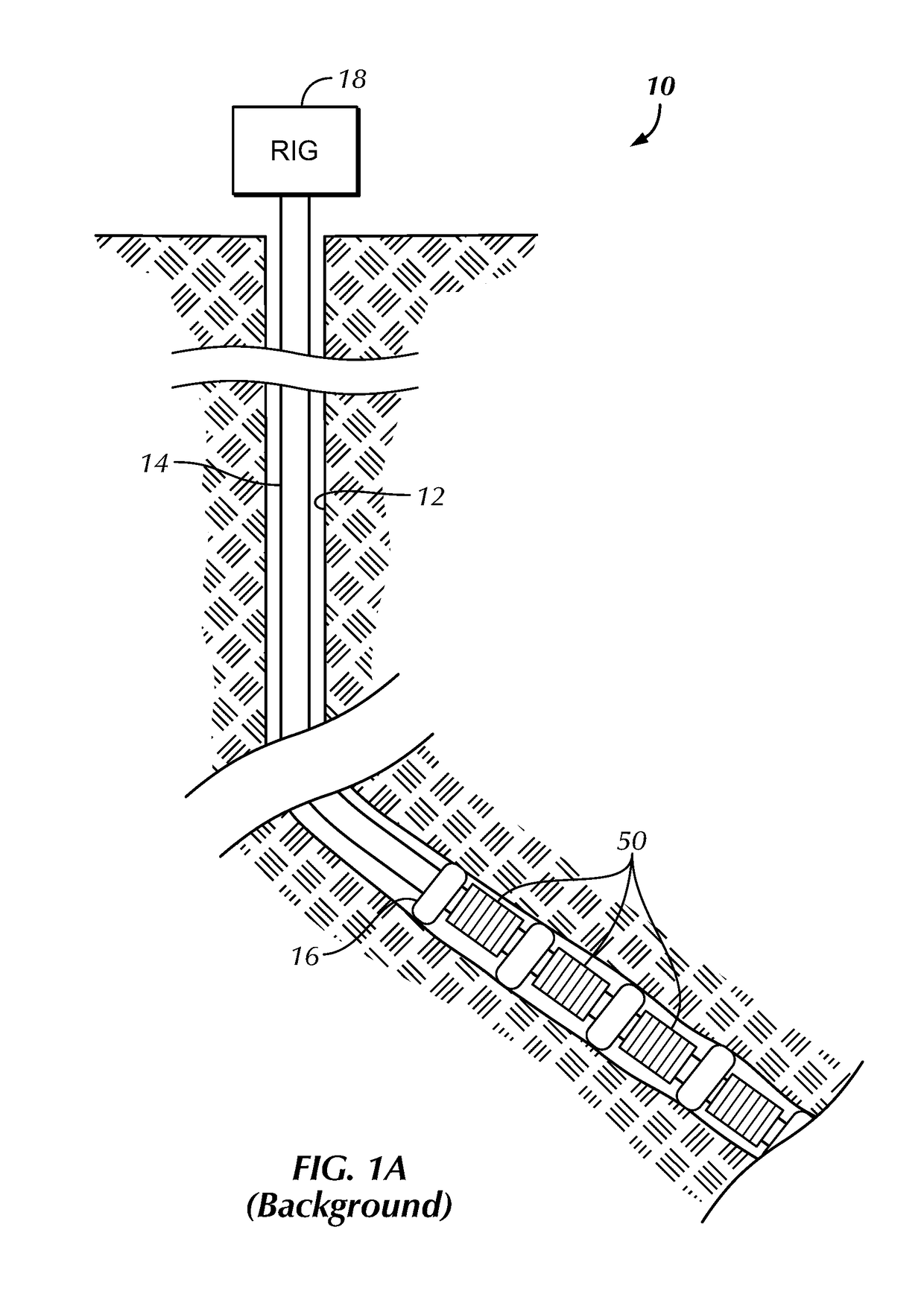
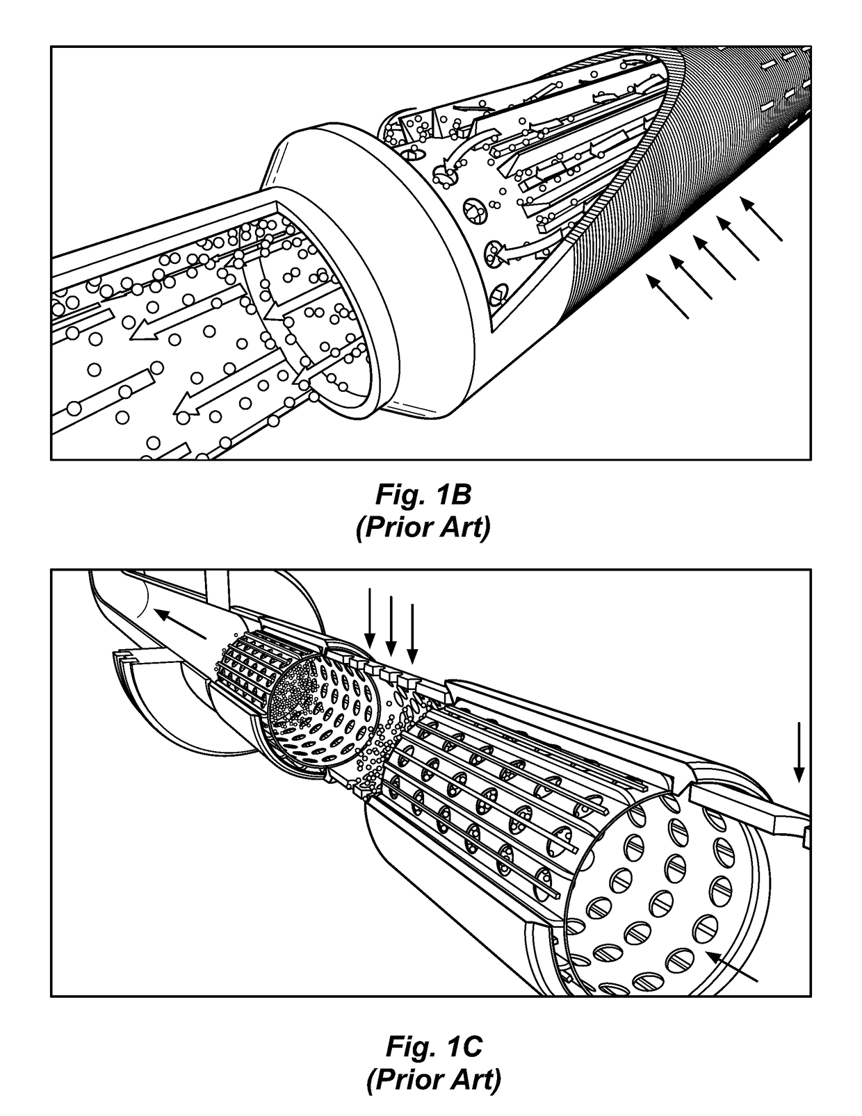
BACKGROUND OF THE DISCLOSURE[0001]Chemical tracers have been used in the oil industry to identify treatment fluid paths and produced fluids downhole. A common method of locating the chemical tracers in the wellbore is to use tracer elements on wellscreens. The wellscreens are then deployed in the wellbore to locate the wellscreens with the chemical tracers in the desired well locations. For example, chemical tracers have been placed on screen joints at the sand face to gather data on the produced fluids.[0002]As background, a completion system 10 in FIG. 1A has completion screen joints 50 deployed on a completion string 14 in a borehole 12. Typically, these screen joints 50 are used for horizontal and deviated boreholes passing in an unconsolidated formation, and packers 16 or other isolation elements can be used between the various joints 50. During production, fluid produced from the borehole 12 directs through the screen joints 50 and up the completion string 14 to the surface ri...

Claims


Application Information

Patent Timeline
Patent Type & Authority Patents(United States)
IPC IPC(8): E21B43/08E21B27/00E21B47/10
CPCE21B43/084E21B47/1015E21B43/08E21B27/00E21B47/11E21B47/10
Inventor DEVARAJAN, KANNANKHOBRAGADE, PANKAJFERNANDES, PRAKASH
Owner WEATHERFORD TECH HLDG LLC
Learn More