A class chair with anti-hunchback function
An anti-hunchback and functional technology, which is used in home appliances, applications, school benches, etc., can solve the problems of poor practicability, limited size of the anti-hunchback seat, and inability to adjust, and achieves good practicability and avoids bending and hunchback. Effect
- Summary
- Abstract
- Description
- Claims
- Application Information
AI Technical Summary
Problems solved by technology
Method used
Image
Examples
Embodiment 1
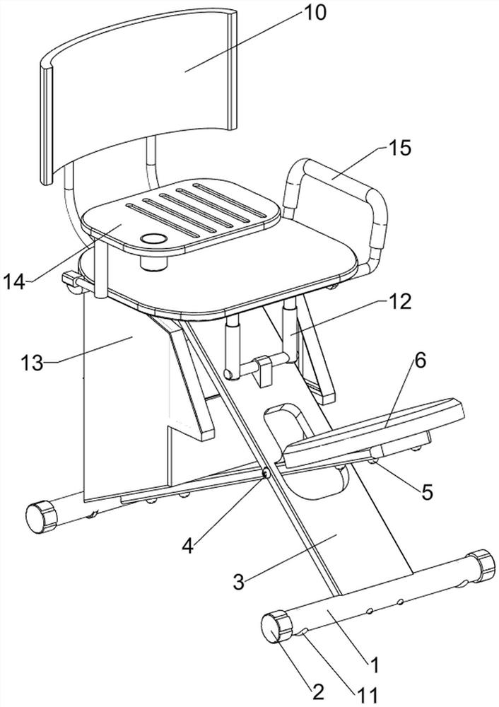
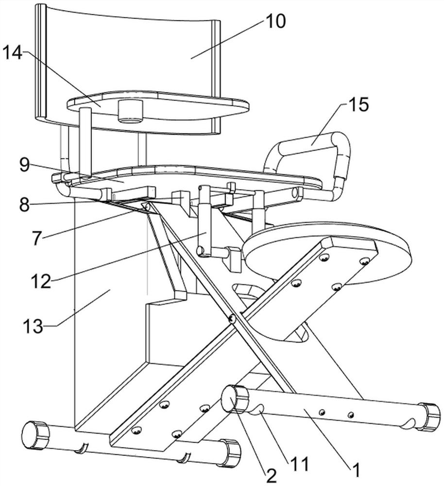
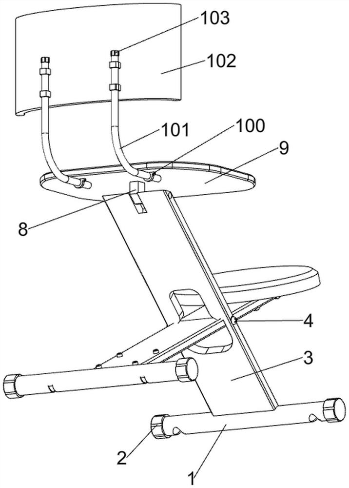
[0034] A class chair with anti-hunchback function, such as Figure 1-5 As shown, it includes a hollow tube 1, a plastic installation head 2, a support plate 3, a first rotating shaft 4, a fixing bolt 5, a first cushion 6, a second rotating shaft 7, a first connecting plate 8, a seat cushion 9, and a backrest mechanism 10 and moving mechanism 11, two hollow tubes 1 left and right sides are provided with plastic installation head 2, two hollow tubes 1 tops are provided with support plate 3, the first rotating shaft 4 is rotatably connected between support plate 3 middle parts, rear Four fixing bolts 5 are installed on the front and rear sides of the bottom of the support plate 3 on the side, and the first cushion 6 is installed between the top of the fixing bolts 5 on the front side. Contact, the rear side of the support plate 3 on the front side is rotationally connected with the second rotating shaft 7, the middle part of the second rotating shaft 7 is connected with the first...
Embodiment 2
[0039] On the basis of Example 1, such as Figure 6-15 As shown, an adjustment mechanism 12 is also included, and the adjustment mechanism 12 includes a first connecting block 120, a fourth rotating shaft 121, a shaft sleeve 122, a third connecting rod 123, a fifth rotating shaft 124, a second connecting block 125 and a first spring 126, a first connecting block 120 is provided on the rear side of the top of the supporting plate 3 on the front side, and a fourth rotating shaft 121 is rotatably connected to the upper part of the first connecting block 120, and the left and right sides of the fourth rotating shaft 121 are symmetrically provided with shaft sleeves 122, and the shaft sleeves The upper parts of 122 are slidingly connected with the third connecting rod 123, the first spring 126 is connected between the third connecting rod 123 and the bushing 122 on the same side, and the fifth rotating shaft is rotatably connected between the upper parts of the third connecting rod ...
PUM
 Abstract
Description
Claims
Application Information
 - R&D
- Intellectual Property
- Life Sciences
- Materials
- Tech Scout
- Unparalleled Data Quality
- Higher Quality Content
- 60% Fewer Hallucinations
Browse by: Latest US Patents, China's latest patents, Technical Efficacy Thesaurus, Application Domain, Technology Topic, Popular Technical Reports.
© 2025 PatSnap. All rights reserved.Legal|Privacy policy|Modern Slavery Act Transparency Statement|Sitemap|About US| Contact US: help@patsnap.com


