
Intelligent observation and identification database system

Active Publication Date: 2004-10-07
FEDERAL LAW ENFORCEMENT DEV SERVICES
View PDF99 Cites 171 Cited by
  • Summary
  • Abstract
  • Description
  • Claims
  • Application Information

AI Technical Summary

Benefits of technology

[0016] A principal advantage of the present invention is the provision of an optical assist method and device which is relatively inexpensive to manufacture, operate, maintain and use and which is formed of relatively inexpensive design and construction which is safe and which is cost efficient in order to fulfill the intended purpose of automatically identifying and tracking a license plate for a vehicle without fear of risk of injury to individuals and / or damage to property.
[0017] Another principal advantage of the present invention is the provision of an optical assist method and device which uses an optical assist camera to recognize and track a license plate number for a vehicle at a distance beyond the normal vision capabilities of an officer.
[0018] Still another principal advantage of the present invention is the provision of an optical assist method and device which may be mounted adjacent to a restricted vehicle access, checkpoint, or security zone which is positioned at a safe distance away from a structure.
[0019] Still another principal advantage of the present invention is the provision of an optical assist method and device which automatically converts an optical image into digital information which is easily stored within a specific accumulated database and compared to the accumulated database for real time retrieval of information concerning a vehicle, a vehicle occupant and / or a class of vehicles in response to a profile search.
[0020] Still another principal advantage of the present invention is the provision of an optical assist method and device which may be hand held or mounted within the interior of a law enforcement, security, or surveillance vehicle or structure.
[0021] Still another principal advantage of the present invention is the provision of an optical assist method and device which is automatically linked or coupled to additional databases for real time retrieval of information.

Problems solved by technology

The failure to use optical input devices has slowed down or delayed the timing for vehicle identification as well as the identification of the vehicle owner and make or model for the vehicle.
In addition the communication of information to an officer or guard as to the criminal history of the likely driver or registered owner of the vehicle was also delayed.
No processor was known to intelligently and / or automatically evaluate or filter information retrieved from a database in real time, to identify a potentially dangerous condition or a necessity to implement a more detailed inquiry related to a vehicle.
Generally this type of optical equipment is expensive and not available for all police or emergency vehicles or restricted access locations.
In addition, no system is known which enables a security, surveillance, or law enforcement officer to either select one of many pre-programmed inquiries based upon profiles, searches, or screening functions in real time to implement a specific customized inquiry of the accumulated database to identify a specific target group of vehicles to receive further investigation.
Generally the use of mirrors for inspection of the undercarriage of a vehicle have failed to provide the opportunity for a complete and detailed inspection of the vehicle.
No intelligent and automatic method of recognizing the existence of an explosive, or the alteration of an undercarriage to hide an explosive, is known to detect the existence of an attempted terrorist attack.
Further, no device has been known to identify and track a person within a security zone absent affirmative actions by the person, or use of a trackable device by the person, such as a personalized keycard.

Method used


Image

  • Intelligent observation and identification database system
  • Intelligent observation and identification database system
  • Intelligent observation and identification database system

Examples


Embodiment Construction

is hereafter described with specific reference being made to the drawings.

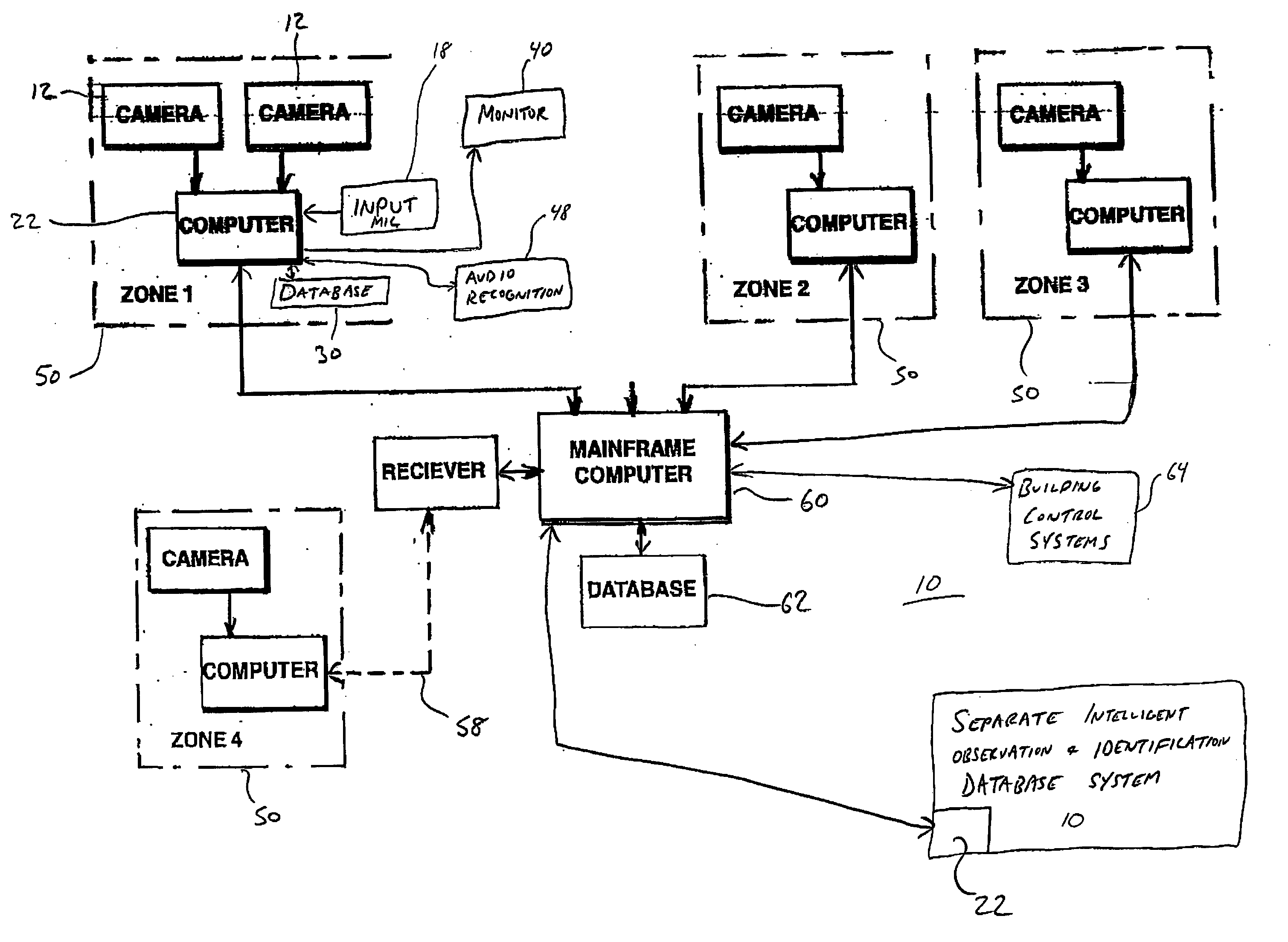
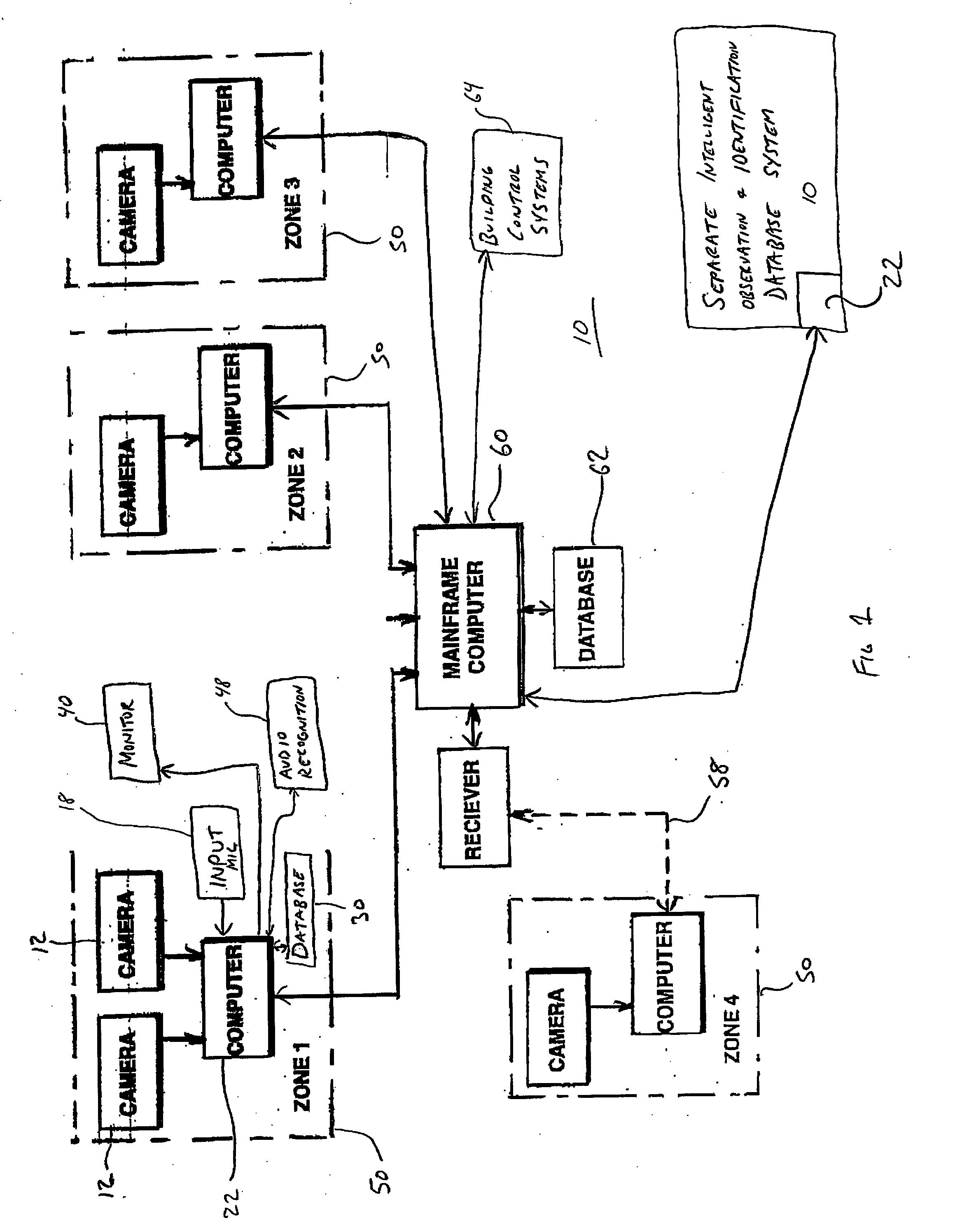
[0058] FIG. 1 shows a schematic view of an intelligent video / audio observation and identification database system according to the present invention.

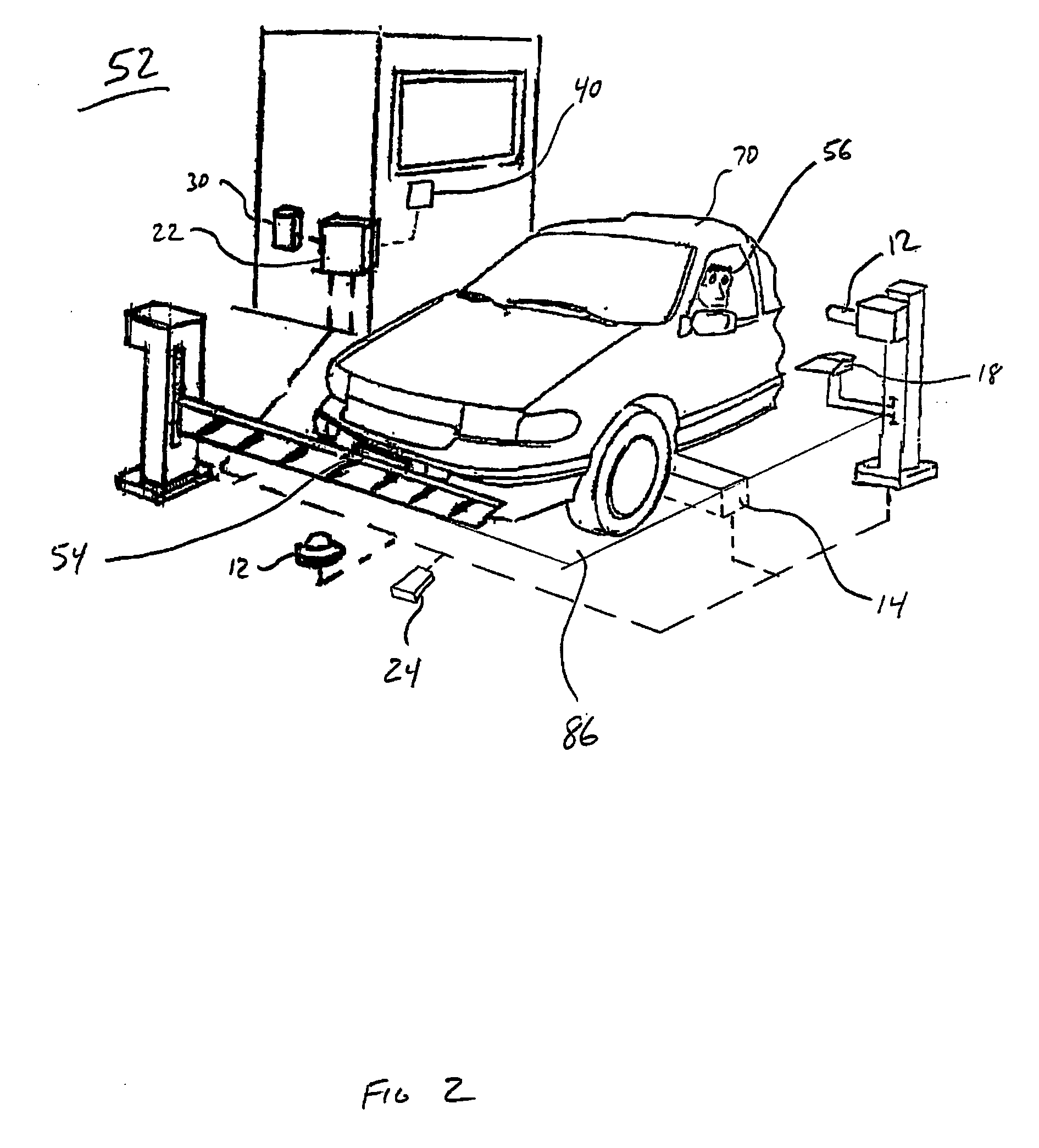
[0059] FIG. 2 depicts an actual installation of an intelligent video / audio observation and identification database system according to the present invention.

[0060] FIG. 3 depicts a mobile intelligent observation and identification database system according to the present invention.

[0061] FIGS. 4 and 4A depict a comparison of vehicle undercarriage images.

[0062] FIG. 5 depicts a mobile vehicle undercarriage observation and identification database system.

[0063] FIGS. 6 and 6A depict a comparison of vehicle side profiles.

[0064] FIG. 7 depicts a mobile intelligent observation and identification database system according to the present invention.

[0065] FIG. 8 depicts an environmental view of a room equipped with an intelligent observation and identification database sys...


PUM


Abstract

An intelligent video / audio observation and identification database system may define a security zone or group of zones. The system may identify vehicles and individuals entering or exiting the zone through image recognition of the vehicle or individual as compared to prerecorded information stored in a database. The system may alert security personnel as to warrants or other information discovered pertaining to the recognized vehicle or individual resulting from a database search. The system may compare images of a suspect vehicle, such as an undercarriage image, to standard vehicle images stored in the database and alert security personnel as to potential vehicle overloading or foreign objects detected, such as potential bombs. The system may track individuals or vehicles within a zone or between zones. The system may further learn the standard times and locations of vehicles or individuals tracked by the system and alert security personnel upon deviation from standard activity.

Description

[0001] This application claims the benefit of Provisional Patent Application Nos. 60 / 405,592 and 60 / 405,379, both filed Aug. 23, 2002, the entire contents of which are incorporated herein by reference.[0002] In the past law enforcement officers, surveillance, or security personnel attempting to identify vehicles and / or occupants of vehicles have observed a license plate without the use of a camera or an optical input device other than eyeglasses. An officer or security guard was thereby required to be sufficiently close to a vehicle to observe the license plate. The presence of the officer was thereby often revealed to the occupant of the vehicle under investigation. The failure to use optical input devices has slowed down or delayed the timing for vehicle identification as well as the identification of the vehicle owner and make or model for the vehicle. In addition the communication of information to an officer or guard as to the criminal history of the likely driver or registered...

Claims


Application Information

Patent Timeline
IPC IPC(8): G07C9/00
CPCG07C9/00158G08B13/19613G08B13/19645G08B13/19647G08B13/19652G08B13/19663H04N7/183G08B31/00G08B13/22Y10S436/90H04N7/18G06F17/30244G08B13/19667G08B13/19671H04N7/181G07C9/37G06F16/50G08B13/19665
Inventor PEDERSON, JOHN C.
Owner FEDERAL LAW ENFORCEMENT DEV SERVICES
Learn More