Radio wave receiving device and radio wave receiving circuit

a radio wave receiving and receiving circuit technology, applied in the field of radio wave receiving devices, can solve the problems of increasing the size of the circuit of the radio wave watch, affecting the reception of the original standard wave, and unable to correct the time, etc., and achieve the effect of simple structur

Active Publication Date: 2006-02-02
CASIO COMPUTER CO LTD
View PDF6 Cites 35 Cited by
  • Summary
  • Abstract
  • Description
  • Claims
  • Application Information

AI Technical Summary

Benefits of technology

[0016] Thereby, the reception signal received by an antenna can be output as the intermediate frequency signal without synthesizing and converting it in the frequency conversion circuit, and can be detected by the detection circuit. That is, the reception of the radio wave composed of a plurality of frequencies can be realized with a simple structure.

Problems solved by technology

The radio wave watch of this kind cannot receive the standard wave in a building in which the radio wave is hard to reach, so that the time may not be corrected.
Thus, if the standard wave and the replayed radio wave are out of phase, the original standard wave may be damaged, thereby interfering with the reception of the original standard wave.
Therefore, two systems of the receiving circuits with different reception frequencies are provided, which increase the size of the circuit of the radio wave watch.

Method used


Image

  • Radio wave receiving device and radio wave receiving circuit
  • Radio wave receiving device and radio wave receiving circuit
  • Radio wave receiving device and radio wave receiving circuit

Examples


first embodiment

[0029] Hereinafter, the first embodiment in which a radio wave watch control device of the present invention is applied will be described in detail by reference to FIGS. 1 to 6. However, the scope of the present invention is not limited to the examples shown in the drawings.

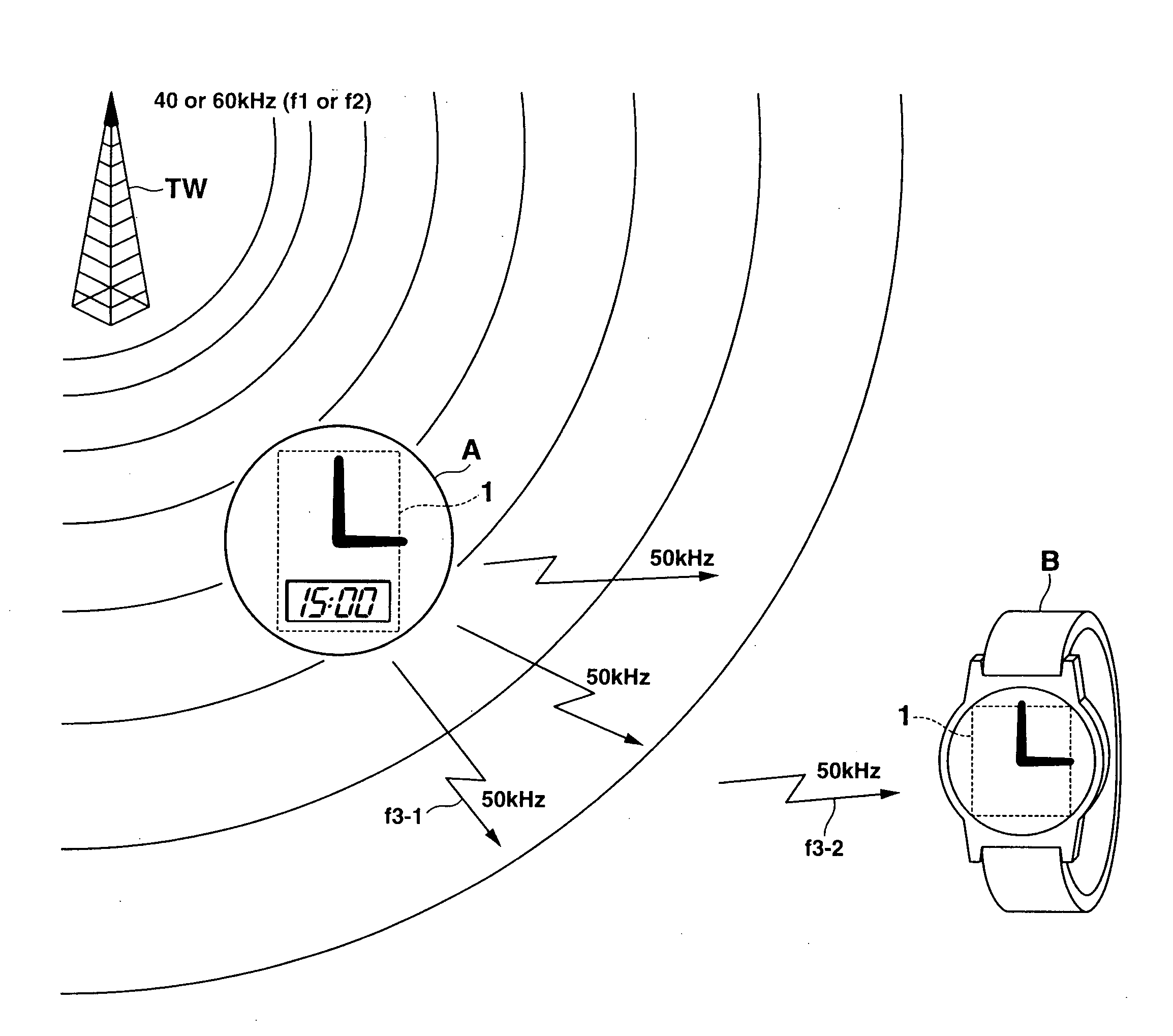
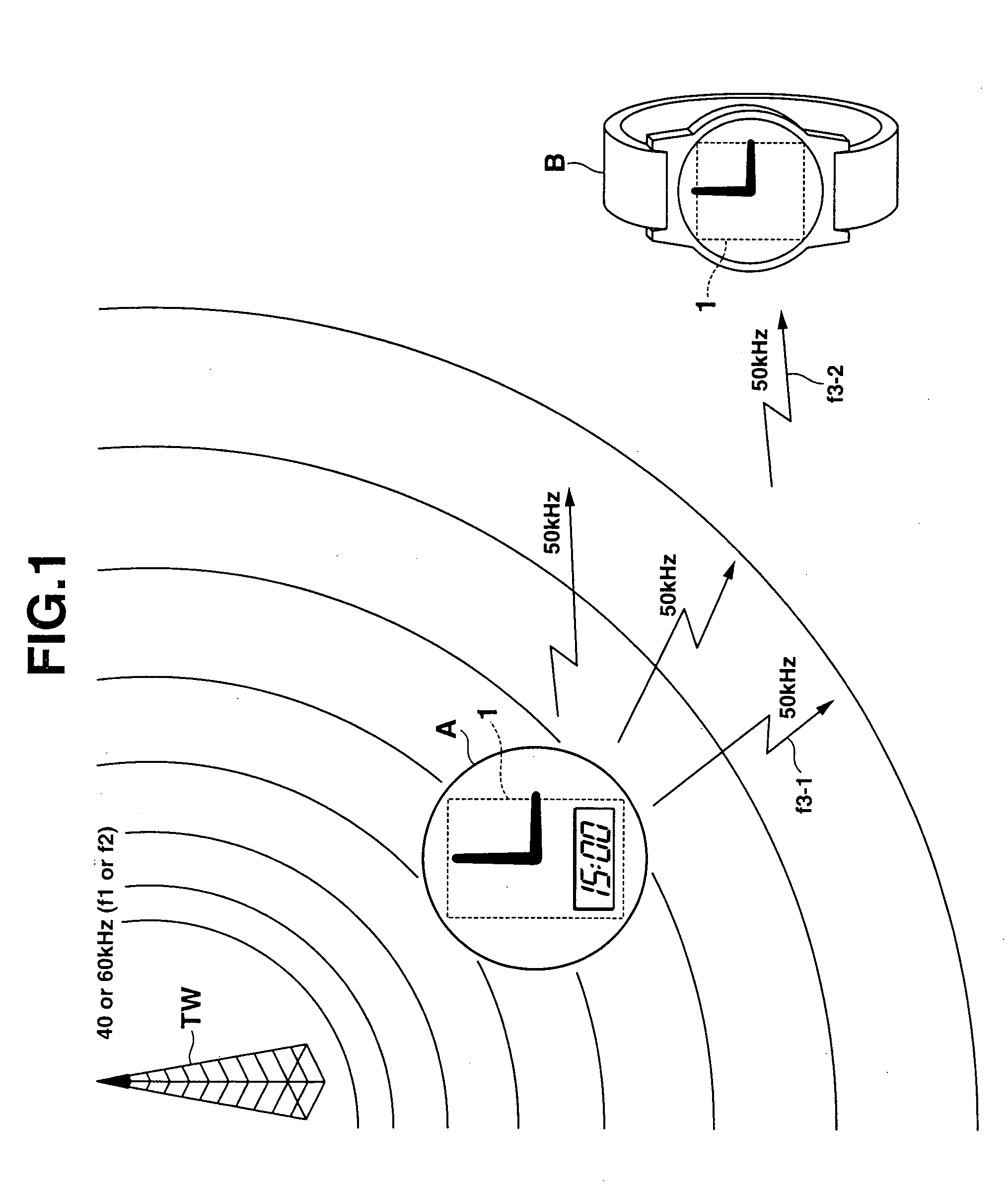
[0030]FIG. 1 is a view for explaining an outline of operations of radio wave watches A and B in each of which the same radio wave watch control device 1 is stored. This figure shows a condition in which a standard wave f1 (or f2) of 40 kHz (or 60 kHz) is transmitted from a transmitting station TW, the radio wave watch A can receive the standard wave f1, and the radio wave watch B cannot receive the standard wave f1.

[0031] Therefore, in the radio wave watch A, the current time which is measured by the radio wave watch control device 1 can be corrected by using the time information included in the standard wave f1. However, the current time in the radio wave watch B cannot be corrected. Thus, in the first embodim...

second embodiment

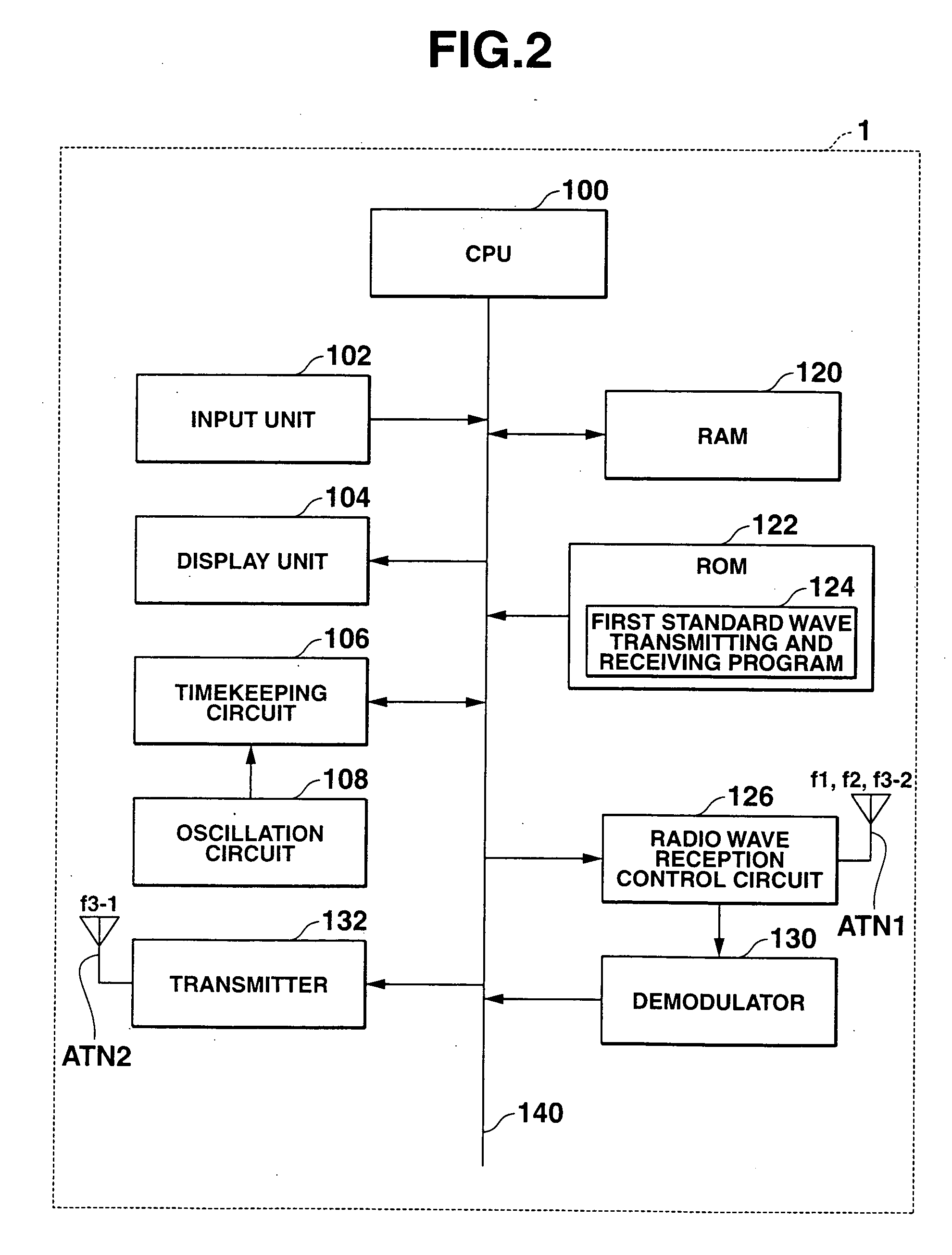
[0093] Next, a radio wave watch control device 1b in the second embodiment will be explained by reference to FIGS. 7 to 12. The radio watch control device 1b in the second embodiment is composed by replacing the CPU 100, the RAM 120, the ROM 122, the radio wave reception control circuit 126, the timekeeping circuit 106, the transmitter 132, the antenna ANT1, the antenna ANT2 in FIG. 2 with a CPU 100b, a RAM 120b, a ROM 122b, a radio wave reception control circuit 126b, a timekeeping circuit 106b, a transmitter 132b, an antenna ANT1b, an antenna ANT2b, respectively, and replacing the demodulator 130 in FIG. 3 with a demodulator 130b. The component that is the same as that of the radio wave watch control device 1 shown in FIG. 2 will be given the same reference numeral and the explanation thereof will be omitted.

[0094]FIGS. 7 and 8 are views for explaining the outline of the operation of a radio wave watches C and D in each of which the same radio wave watch control device 1b is stor...


PUM


Abstract

A frequency switching signal for switching a reception frequency of an antenna based on a reception success or failure signal output from a detection circuit and a standard time code output from a demodulator is output to a reception frequency selection circuit. The reception frequency is switched to the frequency which is the same as an intermediate frequency other than that of the standard radio waves, and at the same time, an output temporarily stopping signal is output to a local oscillation circuit to temporarily stop the output of a local oscillation signal of the local oscillation circuit, enabling to output the reception signal which was received by the antenna as the intermediate frequency signal without synthesizing and converting it in the frequency conversion circuit to be detected by a detection circuit. Thereby, the reception of the radio wave composed of a plurality of frequencies can be realized with a simple structure.

Description

CROSS-REFERENCE TO RELATED APPLICATIONS [0001] This application is based upon and claims the benefit of priority from the prior Japanese Patent Application No. 2004-220375, filed on Jul. 28, 2004, and the entire contents of which are incorporated herein by reference. BACKGROUND OF THE INVENTION [0002] 1. Field of the Invention [0003] The present invention relates to a radio wave receiving device. [0004] 2. Description of Prior Art [0005] Currently, a long-wave standard wave including time data or time code is transmitted in various countries (for example, Japan, America, Germany and the like). In Japan, the long-wave standard waves of 40 kHz and 60 kHz that have been subjected to amplitude modulation by the time code are transmitted from two transmitting stations in Hukushima prefecture and Saga prefecture. [0006] A watch so-called radio wave watch which corrects the time data of a timekeeping circuit has been put to practical use as a radio wave receiving device to receive this sta...

Claims


Application Information

Patent Timeline
Patent Type & Authority Applications(United States)
IPC IPC(8): G04C11/02G04G5/00G04R20/00G04R20/08
CPCG04C9/02G04C11/02G04R20/10G04G7/02G04G5/002G04R20/26
Inventor SOMEYA, KAORU
Owner CASIO COMPUTER CO LTD
Why Eureka
Try Eureka