Multi-camera synchronous triggering device and control method

A synchronous trigger and multi-camera technology, applied in computer control, program control, general control systems, etc., can solve problems such as difficult external standard clock synchronization, high requirements for GPS signal stability, and failure of synchronous triggers

Active Publication Date: 2015-04-08
BEIHANG UNIV
View PDF5 Cites 36 Cited by
  • Summary
  • Abstract
  • Description
  • Claims
  • Application Information

AI Technical Summary

Problems solved by technology

At present, the camera synchronization triggers used are mostly composed of single-chip microcomputers, ARM and other single processors, which can be roughly divided into two categories: one is timed by an on-chip timer or an on-chip clock circuit, which is difficult to synchronize with an external standard clock; the other is based on GPS. The trigger is completed by time, but the stability of the GPS signal is highly required. When the GPS signal is out of lock, the synchronization trigger will fail

Method used


Image

  • Multi-camera synchronous triggering device and control method
  • Multi-camera synchronous triggering device and control method
  • Multi-camera synchronous triggering device and control method

Examples


Embodiment Construction

[0037] The present invention will be further described below in conjunction with the accompanying drawings and specific embodiments.

[0038] The invention provides a multi-camera synchronous triggering device, and the improvement of the invention includes the improvement of the hardware circuit of the multi-camera synchronous triggering device and the improvement of the control method.

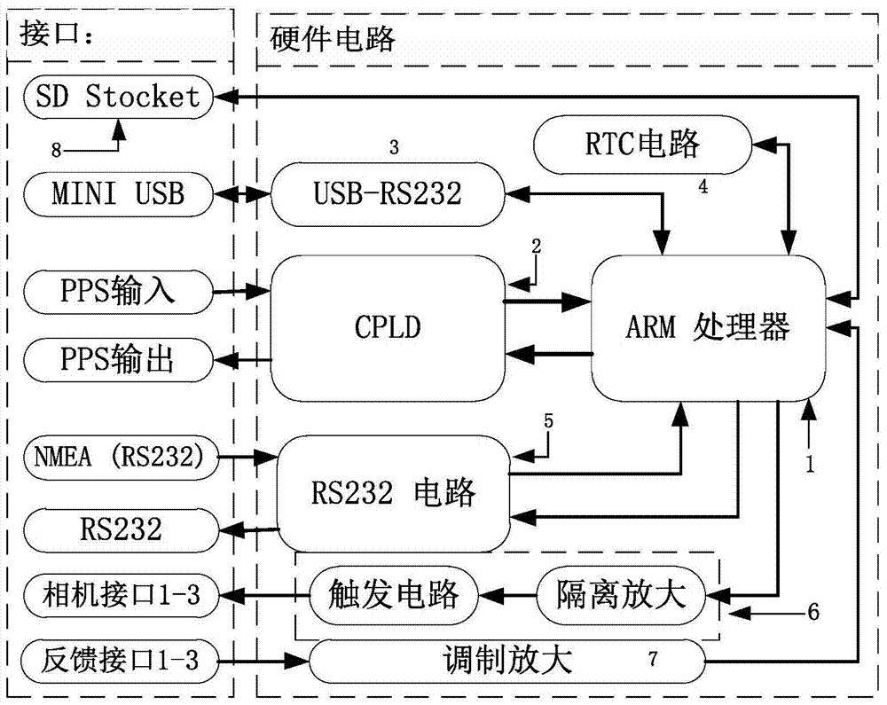
[0039] The hardware circuit includes: ARM processor module 1; CPLD processor module 2; USB-serial port module 3; RTC module 4; RS232 module 5; trigger module 6; signal modulation module 7; SD card module 8, wherein,

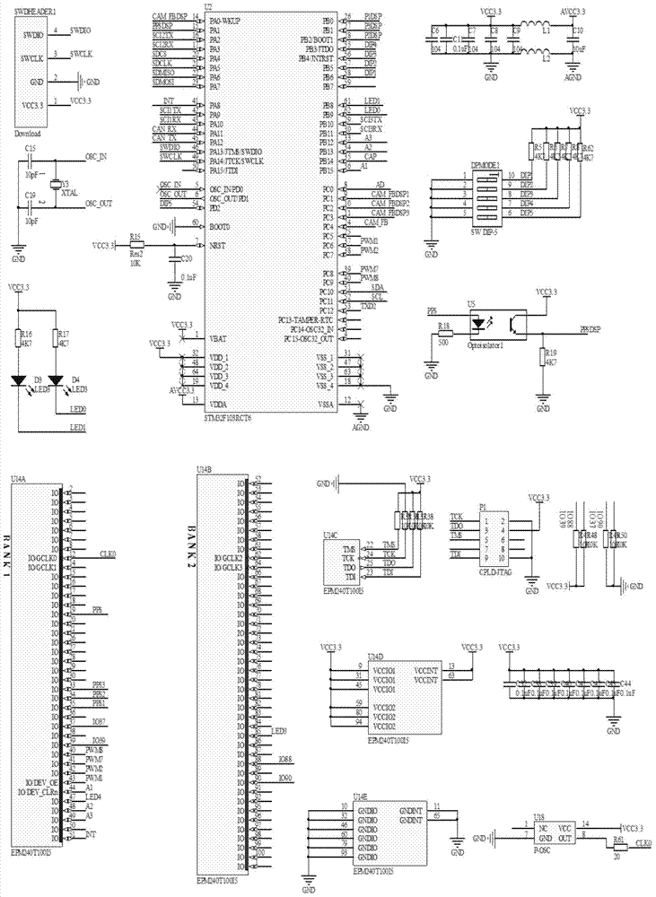
[0040] The ARM processor module 1 is the core controller of the synchronization trigger device of the present invention. Consists of a STM32F103RET6 processor U2, a clock circuit composed of 8M quartz crystal Y3 and two 10pF capacitors C15, C19, a four-terminal SWD debugging port, RC reset circuit R15, C20, five capacitors C6-C10, two inductors L1, L2, two sets of LED circuits ...


PUM


Abstract

The invention discloses a multi-camera synchronous triggering device and a control method, thereby achieving the automatic triggering of a plurality of cameras based on a GPS signal. A synchronous trigger receives GPS serial port information and a PPS signal. According to the GPS signal, the flight height, flight speed and preset overlap ratio of an aircraft are resolved according to the GPS signal, and the photographing intervals between the cameras are calculated. According to the photographing intervals, the synchronous triggering is carried out, and feedback signals exposed by the cameras are read. Moreover, the height, speed and time information of camera triggering are stored in an on-board SD card, thereby facilitating the subsequent data processing. The device irons out the defects that a conventional camera trigger cannot be corresponding to the standard time, cannot achieve the storage of data and is short of an exposure feedback signal detection loop when the conventional camera trigger is based on an off-line clock of a local timer, thereby effectively employing the GPS information to facilitate the subsequent data processing, and improving the reliability.

Description

technical field [0001] The invention relates to a multi-camera synchronous trigger device and a control method, which are applied to the synchronous control of multi-camera aerial photography of unmanned aerial vehicles and unmanned airships, and belong to the field of automatic control. Background technique [0002] In aerial photography systems such as drones and unmanned airships, it is necessary to control the camera for exposure at a certain time interval to ensure effective coverage of the photographed area. At present, the camera synchronization triggers used are mostly composed of single-chip microcomputers, ARM and other single processors, which can be roughly divided into two categories: one is timed by an on-chip timer or an on-chip clock circuit, which is difficult to synchronize with an external standard clock; the other is based on GPS. The trigger is completed by time, but it has high requirements on the stability of the GPS signal. When the GPS signal is out ...

Claims


Application Information

Patent Timeline
Patent Type & Authority Applications(China)
IPC IPC(8): G05B19/042
CPCG05B19/0423
Inventor 胡少兴徐世科刘瑞瑞王都虎
Owner BEIHANG UNIV
Why Eureka
Try Eureka