Automatic peeling device for communication cable end
A cable and terminal technology, which is applied in the field of automatic peeling device for communication cable terminals, can solve the problems of manual clamping and manual peeling, etc.
- Summary
- Abstract
- Description
- Claims
- Application Information
AI Technical Summary
Problems solved by technology
Method used
Image
Examples
Embodiment 1
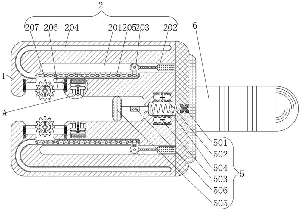
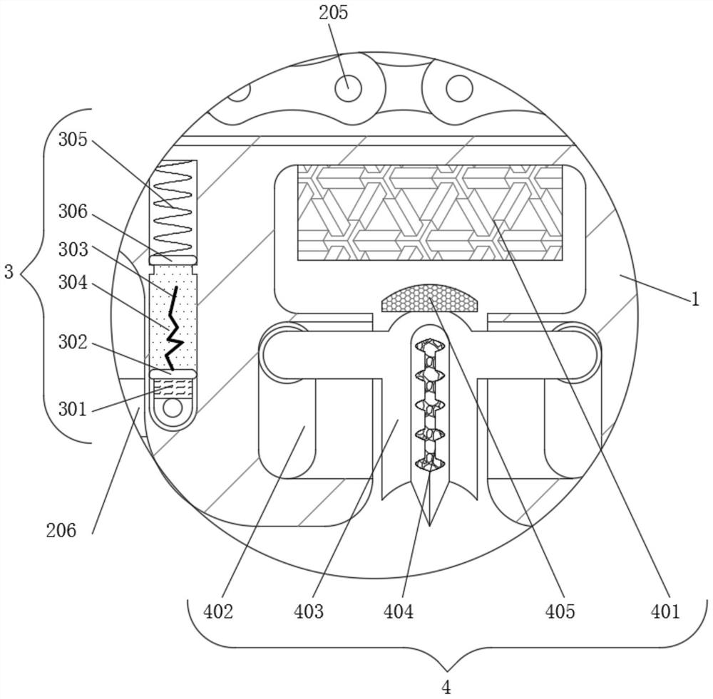
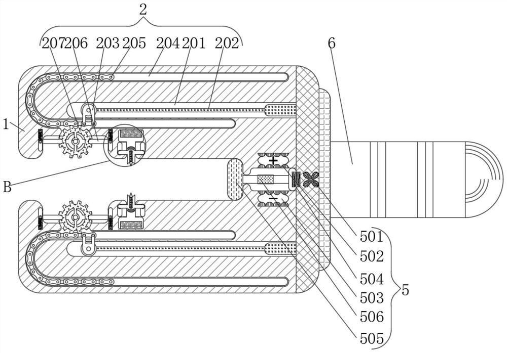
[0029] see Figure 1-4 , an automatic peeling device for communication cable ends, including a housing 1, the shape of the housing 1 is set in a U shape to facilitate the entry of cables, and also includes a transmission mechanism 2, a pushing mechanism 3, and a peeling mechanism 4 , the control mechanism 5, the handle 6, the transmission mechanism 2 is arranged inside the casing 1, the pushing mechanism 3 is arranged inside the casing 1, the peeling mechanism 4 is arranged inside the casing 1, and the control mechanism 5 is arranged inside the casing 1, the handle 6 is fixedly connected to the right side of the housing 1, and the material of the handle 6 is a rubber structure, which is convenient for taking.
[0030] The transmission mechanism 2 includes a sliding groove 201, an electroactive shrinking rod 202, a slider 203, a movable groove 204, a chain 205, a fixed rod 206, and a gear 207. The sliding groove 201 is set inside the housing 1, and the electroactive shrinking r...
Embodiment 2
[0033] see Figure 1-4 , an automatic peeling device for the end of a communication cable, including a housing 1, the shape of the housing 1 is set in a U shape to facilitate the entry of the cable, and also includes a transmission mechanism 2, a pushing mechanism 3, and a peeling mechanism 4 , the control mechanism 5, the handle 6, the transmission mechanism 2 is arranged inside the casing 1, the pushing mechanism 3 is arranged inside the casing 1, the peeling mechanism 4 is arranged inside the casing 1, and the control mechanism 5 is arranged inside the casing 1, the handle 6 is fixedly connected to the right side of the housing 1, and the material of the handle 6 is a rubber structure, which is convenient for taking.
[0034] Peeling mechanism 4 comprises electromagnet 401, motion groove 402, clamping plate 403, heating wire 404, magnetic plate 405, and electromagnet 401 is fixedly connected in the inside of housing 1, and the material of electromagnet 401 is soft iron stru...
Embodiment 3
[0037] see Figure 1-4 , an automatic peeling device for communication cable ends, including a housing 1, the shape of the housing 1 is set in a U shape to facilitate the entry of cables, and also includes a transmission mechanism 2, a pushing mechanism 3, and a peeling mechanism 4 , the control mechanism 5, the handle 6, the transmission mechanism 2 is arranged inside the casing 1, the pushing mechanism 3 is arranged inside the casing 1, the peeling mechanism 4 is arranged inside the casing 1, and the control mechanism 5 is arranged inside the casing 1, the handle 6 is fixedly connected to the right side of the housing 1, and the material of the handle 6 is a rubber structure, which is convenient for taking.
[0038] The transmission mechanism 2 includes a sliding groove 201, an electroactive shrinking rod 202, a slider 203, a movable groove 204, a chain 205, a fixed rod 206, and a gear 207. The sliding groove 201 is set inside the housing 1, and the electroactive shrinking r...
PUM
 Abstract
Description
Claims
Application Information
 - R&D
- Intellectual Property
- Life Sciences
- Materials
- Tech Scout
- Unparalleled Data Quality
- Higher Quality Content
- 60% Fewer Hallucinations
Browse by: Latest US Patents, China's latest patents, Technical Efficacy Thesaurus, Application Domain, Technology Topic, Popular Technical Reports.
© 2025 PatSnap. All rights reserved.Legal|Privacy policy|Modern Slavery Act Transparency Statement|Sitemap|About US| Contact US: help@patsnap.com


