Method for displaying visual detection result of curved object to be detected

A visual detection and display method technology, applied in image data processing, instruments, calculations, etc., can solve the problems that the detection results cannot quickly correspond to the actual position, and the overall detection results cannot be overviewed, so as to achieve the effect of accurate visual detection results

Active Publication Date: 2021-07-30
易思维(杭州)科技有限公司
View PDF3 Cites 0 Cited by
  • Summary
  • Abstract
  • Description
  • Claims
  • Application Information

AI Technical Summary

Problems solved by technology

In this method, only a single image and evaluation results are viewed at a time, and the global detection results cannot be viewed at a glance, and the detection results cannot quickly correspond to the actual position

Method used


Image

  • Method for displaying visual detection result of curved object to be detected
  • Method for displaying visual detection result of curved object to be detected
  • Method for displaying visual detection result of curved object to be detected

Examples


Embodiment Construction

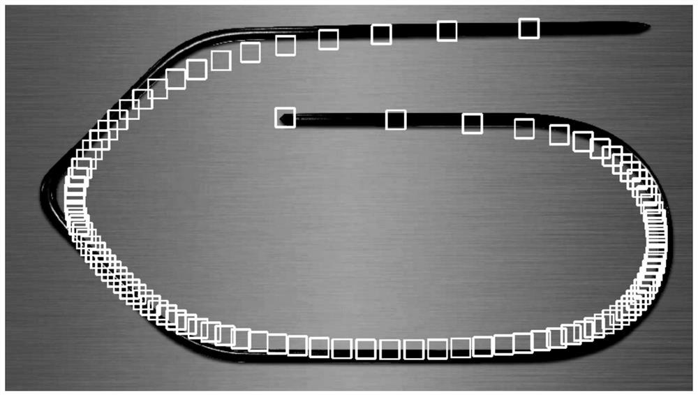
[0030] In this application, the curved object to be tested may be a rubber strip, a weld seam, or the like. The curve in the present application is a curve in the mathematical sense, which is a general term for straight lines and non-straight lines.

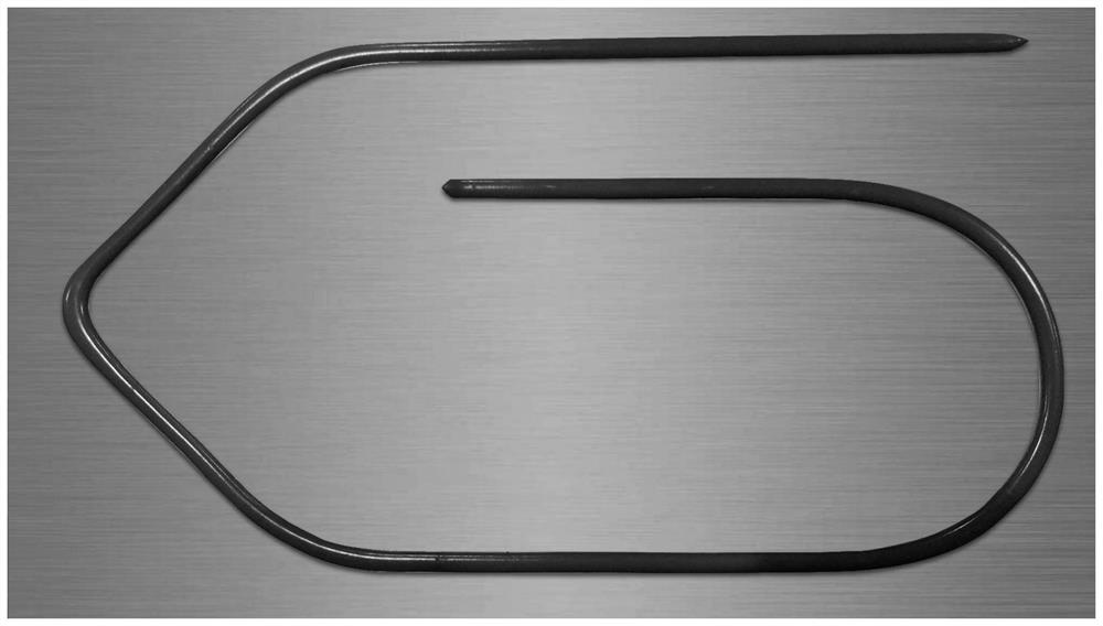
[0031] The method claimed in the present application is explained below with the display of the visual inspection results of the shaped rubber strips in the accompanying drawings. Other shapes, such as straight line, S-shape, and Z-shape, are applicable to the display method of this application.

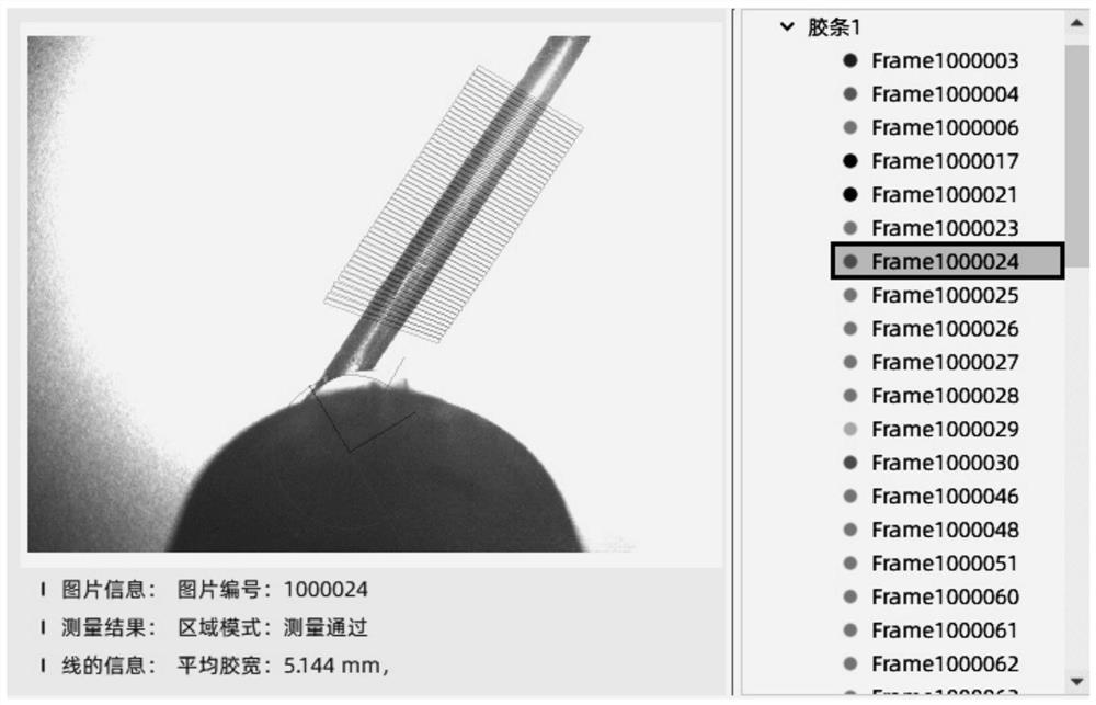
[0032] The object to be detected is a section of glue, the glue gun is fixed at the end of the robot, and the visual inspection equipment is ring-shaped, which is set on the glue gun, so that the visual inspection equipment can simultaneously detect the glue quality while applying glue. In order to ensure the uniformity of gluing, the robot moves at a constant speed, and then drives the visual inspection equipment to move at a constant...


PUM


Abstract

The invention discloses a method for displaying a visual detection result of a curved to-be-detected object, which comprises the following steps: fixing visual detection equipment on a robot, synchronously moving with the tail end of the robot at a constant speed, and acquiring an image of a corresponding position of the curved to-be-detected object by the visual detection equipment; distributing a plurality of display frames uniformly on the overview map, and associating the display frames with the detection results of the corresponding positions, wherein the plurality of display frames distributed on the overview map are obtained by performing the following steps in advance before testing: 1) obtaining the overview map of a curve-shaped object to be tested, manually marking a head end point and a tail end point, manually marking a schematic point along the curve-shaped object to be tested, and marking all points as a first type of points, wherein the first type of points can feed back shape features of the curve-shaped object to be measured; 2) uniformly inserting a second type of points between two adjacent first type of points; and 3) drawing a display frame according to the positions of all the first and second class points. According to the method, the display position corresponds to the visual detection result, and the actual position of the detection result on the part can be displayed in real time.

Description

technical field [0001] The invention relates to the field of product quality inspection, in particular to a display method for visual inspection results of a curved object to be tested. Background technique [0002] At present, when displaying the visual inspection results of curved objects (such as rubber strips, welds, etc.), the NURBS (Non Uniform Rational B-spline) method is usually used on the overview map, also known as non-uniform rational B-spline curve , the marker points set by it present non-uniformity on the image (such as figure 1 As shown), the distribution points of the straight line segment are too loose, and the points distribution of the curved segment is dense, which is not the same as the actual detection process to obtain the image. In actual inspection, the robot moves at a constant speed relative to the workpiece to be processed. The visual inspection equipment is generally fixed at the end of the robot and moves synchronously with the end of the robo...

Claims


Application Information

Patent Timeline
IPC IPC(8): G06T7/00G06T7/70G06T7/20
CPCG06T7/0004G06T7/70G06T7/20
Inventor 庄洵张国涛徐航王立
Owner 易思维(杭州)科技有限公司
Why Eureka
Try Eureka