Check patentability & draft patents in minutes with Patsnap Eureka AI!

Rotor for inductive angular displacement sensor

An angular displacement sensor and inductive technology, applied in the direction of converting sensor output, using electric/magnetic devices to transfer sensing components, instruments, etc., can solve problems such as limited cost, not strong, and unsuitable winding rotor resolvers

Active Publication Date: 2021-08-17
SAFRAN ELECTRONICS & DEFENSE
View PDF7 Cites 0 Cited by
  • Summary
  • Abstract
  • Description
  • Claims
  • Application Information

AI Technical Summary

Problems solved by technology

[0011] The resolver is a more expensive and less robust device than an inductive angular displacement sensor
Therefore, wound rotor solvers are not suitable where angular displacement must be measured in harsh environments, such as in aviation, aerospace or military, or where cost is limited

Method used


Image

  • Rotor for inductive angular displacement sensor
  • Rotor for inductive angular displacement sensor
  • Rotor for inductive angular displacement sensor

Examples


Embodiment Construction

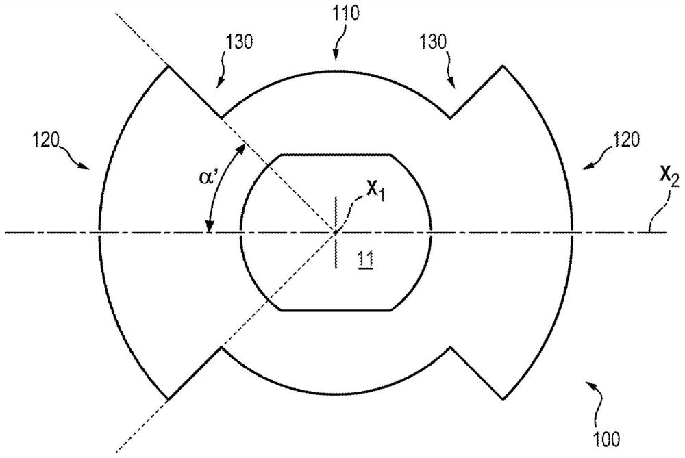
[0042] exist Figure 4 and Figure 5 The rotor 1 for an inductive angular displacement sensor, shown by way of non-limiting example in , is unwound, rotatably movable about a first axis X1 and symmetrical about this first axis X1. Rotor 1 has:

[0043] - central part 10,

[0044] - two movable parts 20 on either side of the central part 10 with respect to the first axis X1, each movable part comprising:

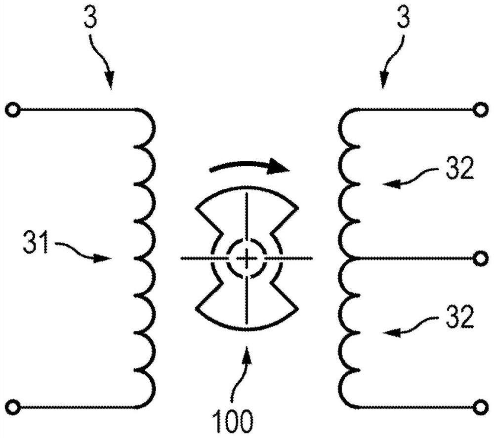
[0045] - an outer surface 21 configured to face the inner surface 33 of the stator 3 of the inductive angular displacement sensor,

[0046] - Two connecting walls 221 , 222 for connecting the outer surface 21 to the central part 10 .

[0047] The rotor 1 also has axial symmetry about a second axis X2 contained in a plane P perpendicular to the first axis X1 and passing through the two movable parts 20 . In the normal plane P, each connecting wall 221 , 222 forms an angle α greater than 45° with the second axis X2. In other words, each connecting wall 221 , 222 forms an ...


PUM


Abstract

The present invention relates to an unwound rotor (1) for an inductive angular displacement sensor, which rotor is rotatably movable about a first axis (X1) and symmetrical with respect to the first axis (X1), the rotor (1) having: a central portion (10), two active portions (20) on either side of the central portion (10) relative to the first axis (X1), each active portion (20) comprising an outer surface (21) and two connecting walls (221, 222) connecting the outer surface (21) to the central portion (10), the rotor (1) being characterised in that in a plane (P) normal to the first axis (X1), each connecting wall (221, 222) forms an angle (a) greater than 45 degrees with a second axis (X2). The invention also describes an inductive angular displacement sensor comprising such a rotor.

Description

technical field [0001] The invention relates to the field of inductive angular displacement sensors. Background technique [0002] Inductive angular displacement sensors (rotary variable differential transformers, RVDTs) are commonly used to measure the angular displacement of one component relative to another. [0003] In known manner, an inductive angular displacement sensor comprises a rotor and a stator. The stator, made of ferromagnetic material, includes a primary winding and two secondary windings and defines a cavity in which the rotor is placed. The rotor, made of ferromagnetic material, is unwound (ie, has no windings) and moves rotationally within the stator. The rotor is integral with the part whose angular displacement is to be measured. [0004] Such as figure 1 As shown schematically, the inductive angular displacement sensor works according to the principle of a transformer. The primary winding 31 of the stator 3 is subjected to a current induced by elec...

Claims


Application Information

Patent Timeline
Patent Type & Authority Applications(China)
IPC IPC(8): G01D5/20G01D5/22
CPCG01D5/2291G01D5/2053
Inventor 马修·施密特伯纳德·拉布雷特帕特里克·贝松蒂埃里·贝塞德
Owner SAFRAN ELECTRONICS & DEFENSE
Features
  • R&D
  • Intellectual Property
  • Life Sciences
  • Materials
  • Tech Scout
  • Unparalleled Data Quality
  • Higher Quality Content
  • 60% Fewer Hallucinations
Learn More