Check patentability & draft patents in minutes with Patsnap Eureka AI!

Detector

A technology for detectors and detection circuits, applied in the field of logic detectors, can solve the problems of increased power consumption, increased response speed of amplifiers, and inability to detect rapid power droop, etc.

Active Publication Date: 2021-09-07
SONY SEMICON SOLUTIONS CORP
View PDF13 Cites 0 Cited by
  • Summary
  • Abstract
  • Description
  • Claims
  • Application Information

AI Technical Summary

Problems solved by technology

[0005] However, in the case of detecting power supply droop using an analog circuit, the response of the amplifier is poor, and in some cases, rapid power droop cannot be detected
On the other hand, if the response speed of the amplifier increases, power consumption (current consumption) may increase

Method used


Image

  • Detector
  • Detector
  • Detector

Examples


no. 1 approach

[0057] 2. First Embodiment (Example 1 of Detector)

no. 2 approach

[0058] 3. Second Embodiment (Example 2 of Detector)

[0059]4. Third Embodiment (Example 3 of Detector)

[0060]

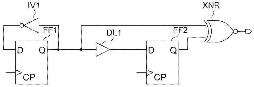
[0061] In the conventional way of detecting a glitch voltage using an analog circuit, the response of the amplifier is poor when a power supply droop is detected, and in some cases, rapid power supply droop cannot be detected. It should be noted that the rapid power droop refers to a power droop in which the voltage drops instantaneously. Further, if the response speed of the amplifier increases, power consumption (current consumption) may increase. On the other hand, in the method of detecting power droop using a logic circuit, the delay time of the logic element is used to intentionally cause violation of flip-flop setting or violation of hold setting, and thereby, a glitch circuit is detected.

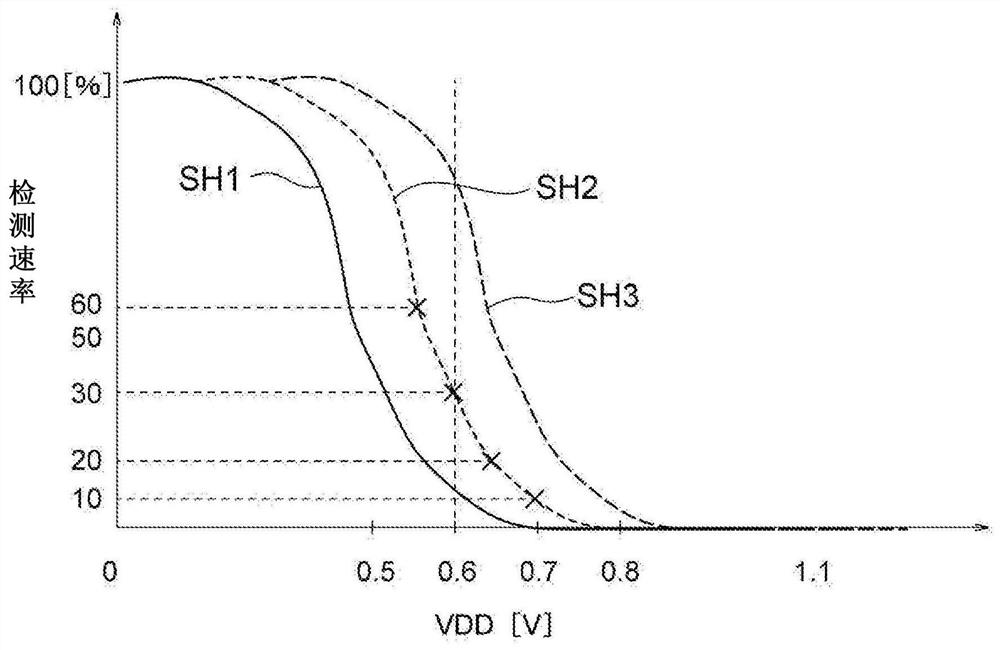
[0062] However, the delay time in logic elements depends on process and temperature, and there are variations inside each semiconductor device (integrated circuit)....

no. 3 approach

[0147]

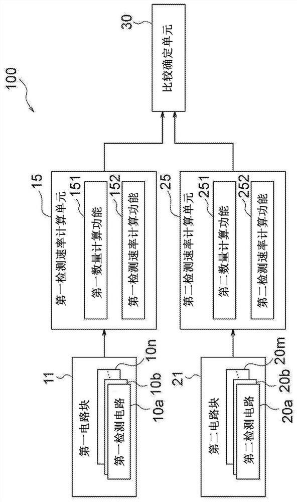
[0148] The power supply circuit according to the third embodiment of the present technology is the same detector as the first embodiment, but: the detector includes a reference voltage generating circuit; the input voltage is a power supply voltage and is also supplied to the reference voltage generating circuit; the reference voltage is generated The circuit generates a predetermined reference voltage based on the input voltage; each of the plurality of first detection circuits operates using a clock having a frequency substantially equal to a frequency of a system clock used to operate the processing circuit; the plurality of second detection circuits Each second detection circuit in the circuit operates using a clock having a frequency approximately equal to that of the system clock; when the power supply voltage fluctuates, the first detection rate calculation unit calculates the first detection rate calculation unit based on the power supply voltage after the pow...


PUM


Abstract

Provided is a detector that can detect that a voltage is out of a guaranteed operation voltage even when a delay time of a logic element caused by a reduction in a power supply voltage varies due to an external factor. The detector comprises: a plurality of first detection circuits; a first detection rate calculation unit; a plurality of second detection circuits; a second detection rate calculation unit; and a comparison-and-determination unit. The present invention provides a detector, wherein each of the plurality of first detection circuits detects whether or not an input voltage is a value outside a guaranteed operation range for normal operation; the first detection rate calculation unit calculates first detection rates of which the number is the number of the detected first detection circuits; each of the plurality of second detection circuits detects whether or not a predetermined reference voltage is lower than a threshold voltage; the second detection rate calculation unit calculates second detection rates of which the number is the number of the detected second detection circuits; and the comparison-and-determination unit determines that a value of the input voltage is equal to or less than a value of the threshold voltage when the first detection rate and the second detection rate are substantially equal to each other.

Description

technical field [0001] The present technology relates to detectors, and more particularly, to a logic detector using digital detection circuits. Background technique [0002] In a semiconductor device (integrated circuit) in which a central processing unit (CPU), a digital signal processor (DSP), etc. are mounted, the power-supply droop during the operation of the logic circuit under consideration is used to determine the Guaranteed operating voltage. [0003] In recent years, in order to reduce power consumption in semiconductor devices (integrated circuits), it is necessary to minimize guaranteed operating voltages in semiconductor devices (integrated circuits). Therefore, in the case where the voltage supplied to the logic circuit is outside the guaranteed operating range, a circuit that detects the supply voltage outside the guaranteed operating range is required. [0004] Here, there is known a phenomenon called power droop in which a voltage input to a semiconductor ...

Claims


Application Information

Patent Timeline
Patent Type & Authority Applications(China)
IPC IPC(8): G01R19/165H01L21/82H01L21/822H01L27/04
CPCH01L21/82H01L21/822H01L27/04G01R19/16552G01R19/1659G01R19/16576
Inventor 中原宏徳
Owner SONY SEMICON SOLUTIONS CORP
Features
  • R&D
  • Intellectual Property
  • Life Sciences
  • Materials
  • Tech Scout
  • Unparalleled Data Quality
  • Higher Quality Content
  • 60% Fewer Hallucinations
Learn More